

|
|
Indicates a reference to a section with important information and safety warnings |
|
|
Arrow indicating that the section continues on the next page. |
|
|
Arrow marking the end of a section. |
|
|
The symbol indicates situations in which the vehicle must be stopped as quickly as possible. |
| ® | The symbol indicates registered trademarks. However, the absence of this symbol does not constitute a waiver of any rights associated with intellectual property. |
|
⇒
|
Cross-reference to a red, orange, or yellow warning in the same section or on the stated page, pointing out possible risks that can cause serious personal injuries and how to help prevent them. |
|
⇒
|
Cross reference to a Notice about possible property damage, in the same section or on the stated page. |
|
|
Used on vehicle labels and indicates the availability of additional important information and warnings in this Owner’s Manual. |

 Danger!Texts with this symbol contain information regarding hazardous situations which will cause death or severe injuries if not avoided.
 WarningTexts with this symbol contain information regarding hazardous situations which could cause death or severe injuries if not avoided.
 CautionTexts with this symbol contain information regarding hazardous situations which could cause minor or moderate injuries if not avoided.
 NoteTexts with this symbol contain information regarding situations which could cause vehicle damage if not avoided.
 Texts with this symbol contain information about the environment and how you can help to protect it.
 Texts with this symbol contain supplementary information.
| This Volkswagen vehicle provides advanced technology incorporating many convenience features for you to enjoy in your daily driving. |
| Please carefully read and follow the information in this Owner's Manual. It will help you both to become more familiar with your vehicle and to recognize and avoid situations that could endanger you and others. |
| If you have questions about your vehicle or if you believe that the manual is not complete, please contact your authorized Volkswagen dealer or your authorized Volkswagen Service Facility. Authorized Volkswagen dealers and authorized Volkswagen Service Facilities always welcome your questions, suggestions, and constructive criticism. |
| We hope you enjoy your vehicle and we wish you many years of safe and enjoyable driving. |
|
Volkswagen AG Volkswagen de México, S.A. de C.V. |
All options and models are described without identification as optional equipment or model versions. Some of the described equipment may not be installed on your vehicle or may be available at a later time or only in certain markets. Please consult the sales documents regarding your vehicle's equipment and options and contact your authorized Volkswagen dealer or authorized Volkswagen Service Facility for more information.
All information in this Manual corresponds to information available as of the editorial deadline. Due to ongoing vehicle development, there may be differences between your vehicle and the information in this Manual. No legal obligations or commitments can be derived from the information, illustrations, or descriptions in this Manual.
If you sell or lend your vehicle, please make sure that the complete Manual set is in the vehicle.
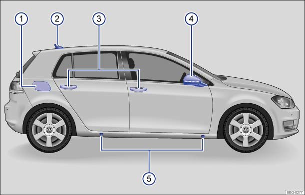 Fig. 1 Vehicle side overview.
Key to ⇒ Fig. 1 :
 Fuel filler flap ⇒ Refueling
  Roof antenna ⇒ Consumer information
  Outside door handles ⇒ Doors
Outside mirror ⇒ Mirrors
 Lift points for the jack ⇒ Changing a wheel
 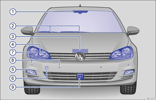 Fig. 2 Vehicle front overview.
Key to ⇒ Fig. 2 :
Inside mirror with sensor or camera on the mirror base for:
Windshield wipers ⇒ Windshield wipers and washer Engine hood release ⇒ Working in the engine compartment Headlights (on left and right) ⇒ Lights Fog lights/static cornering lights (on left and right, if equipped) ⇒ Lights  Threaded hole for the front towing eye (behind cover) ⇒ Towing
  Side marker lights (on left and right) ⇒ Lights
Sensors for:

Sensor for:
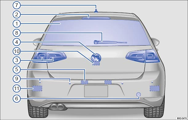 Fig. 3 Vehicle rear overview.
Key to ⇒ Fig. 3 :
Rear window:
High-mounted brake light ⇒ Braking and parking Taillights (on left and right) ⇒ Lights , ⇒ Replacing light bulbs Volkswagen emblem for opening the trunk lid ⇒ Trunk lid License plate lights ⇒ Lights , ⇒ Replacing light bulbs Threaded hole for the rear towing eye (behind cover) ⇒ Towing Roof antenna ⇒ Consumer information Rear windshield wiper ⇒ Windshield wipers and washer Sensors for:
 Area for the Rear View Camera system (if equipped) ⇒ Rear View Camera system
  Sensors for the Blind Spot Monitor with Rear Traffic Alert (approximate location on left and right, if equipped) ⇒ Blind Spot Monitor with Rear Traffic Alert
 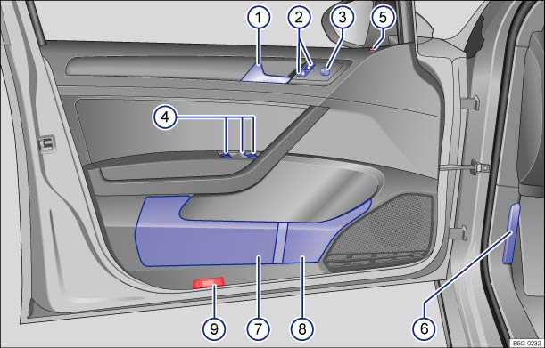 Fig. 4 Overview of controls in the driver door.
Key to ⇒ Fig. 4 :
Door handle ⇒ Doors Power locking button for locking and unlocking the vehicle Knob for adjusting the outside mirrors ⇒ Mirrors
Switches for operating the power windows ⇒ Power windows
Indicator light for the power locking system ⇒ Power locking system Lever for releasing the engine hood ⇒ Working in the engine compartment Storage compartment ⇒ Storage areas Bottle holder ⇒ Cup holders Reflector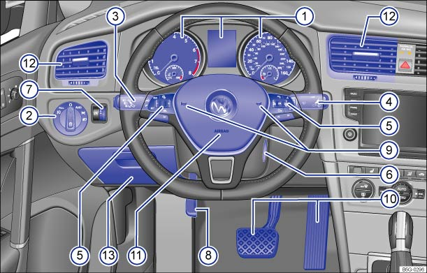 Fig. 5 Driver side overview.
Key to ⇒ Fig. 5 :
Instrument cluster:
Headlight switch ⇒ Lights
Lever for ⇒ Lights
Windshield wiper and washer lever ⇒ Windshield wipers and washer
Multi-function steering wheel controls (if equipped) ⇒ Volkswagen Information System , ⇒ Cruise control
Ignition switch (vehicles without Keyless Access) or location for the emergency start feature for the Keyless Access system ⇒ Starting and stopping the engine Dimmer control for the instrument and switch illumination Lever for the adjustable steering wheel ⇒ Adjusting the seating position HornPedals ⇒ Shifting Driver front airbag ⇒ Airbag system  Air vents
  Storage compartment ⇒ Storage areas
 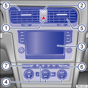 Fig. 6 Overview of the upper center console.
Key to ⇒ Fig. 6 :
Button for the emergency flashers PASSENGER AIR BAG Infotainment system ⇒ Infotainment system
Controls for:
Air vents Passenger seat heating button Driver seat heating button 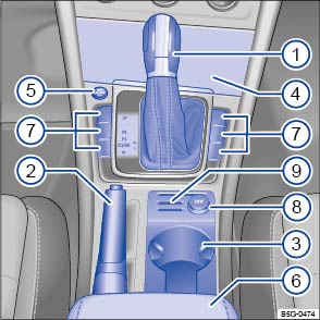 Fig. 7 Overview of the lower center console (Golf and Golf GTI models).
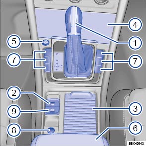 Fig. 8 Overview of the lower center console (Golf R models).
Key to ⇒ Fig. 7 (Golf and Golf GTI models only):
Lever for:
Parking brake lever ⇒ Braking and parking Storage compartment with cup holders ⇒ Cup holders Storage compartment ⇒ Storage areas
Starter button (for vehicles with Keyless Access) Center armrest ⇒ Center armrest (Golf, Golf GTI)
Buttons for:
12 Volt socket ⇒ Power outlets Coin holders ⇒ Coin holders in the front center console (Golf, Golf GTI) Key to ⇒ Fig. 8 (Golf R models only):
Lever for:
Electronic parking brake Storage compartment with cup holders ⇒ Cup holders Storage compartment ⇒ Storage areas
Starter button (for vehicles with Keyless Access) Center armrest ⇒ Center armrest (Golf R) Buttons for:
12 Volt socket ⇒ Power outlets Auto Hold button 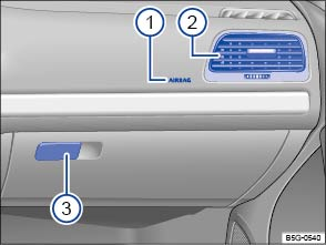 Fig. 9 Overview of the front passenger side.
Key to ⇒ Fig. 9 :
Passenger front airbag location in the instrument panel (approximate) ⇒ Airbag system Air vent Opening handle for the glove compartment ⇒ Storage areas | Symbol | Meaning |
|---|---|
|
|
Interior and reading lights ⇒ Lights . |
|
|
Power sunroof ⇒ Power sunroof . |
|
OR: |
3-button module for vehicles with Car-Net⇒ Volkswagen Car-Net . |
Warning and indicator lights notify you of warnings ⇒ , malfunctions ⇒ , or certain functions. Some warning and indicator lights come on when the ignition is switched on and should go out when the engine is running or when the vehicle is moving.
Additional text messages appear in the instrument cluster of appropriately equipped vehicles to give more information or prompt you to take certain actions ⇒ Instrument cluster .
Depending on the vehicle options, a symbol may appear in the instrument cluster instead of a warning light.
In addition, a warning chime or other acoustic warning sounds when certain warning and indicator lights go on.
| Symbol |
Meaning ⇒ , ⇒
|
|---|---|
|
|
Central warning light: Read and follow the text messages in the instrument cluster display. |
|
|
Parking brake engaged ⇒ Braking and parking . |
|
|
Brake fluid level too low or brake system malfunction ⇒ Braking and parking . |
|
|
Engine coolant level too low, engine coolant temperature too high, or engine coolant system malfunction⇒ Engine coolant . |
|
|
Engine oil pressure too low⇒ Engine oil . |
|
|
Lights up: Steering system malfunction ⇒ Steering . |
|
Flashes: Electronic steering column lock malfunction ⇒ Steering . |
|
|
|
Driver and/or passenger safety belts not buckled ⇒ Safety belts . |
|
|
Alternator malfunction⇒ Vehicle battery . |
|
|
Brake or take action to avoid the vehicle ahead! Front Assist Forward Collision Warning (if equipped)⇒ Forward Collision Warning (Front Assist) . |
|
|
Brake! Depress brake pedal. ACC driver intervention warning ⇒ Adaptive Cruise Control (ACC) . |
|
|
Lights up: ESC malfunction or ESC switched off by the system ⇒ Braking and parking . OR: the vehicle battery has been reconnected ⇒ Braking and parking . |
| Flashes: ESC or ASR is working ⇒ Braking and parking . | |
|
|
ASR manually deactivated ⇒ Braking and parking . |
| OR: ESC Sport mode manually activated ⇒ Braking and parking . | |
|
|
ABS malfunction ⇒ Braking and parking . |
|
|
Electronic parking brake malfunction (if equipped)⇒ Braking and parking . |
|
|
Central caution light: Read and follow the text messages in the instrument cluster display. |
|
|
One or more driving lights burned out⇒ Replacing light bulbs . |
| Light malfunction, excluding AFS⇒ Lights . | |
|
|
Not enough windshield washer fluid⇒ Windshield wipers and washer . |
|
|
Lights up: Engine control malfunction ⇒ Engine control and emission control system . |
| Flashes: Misfire ⇒ Engine control and emission control system . | |
|
|
Engine control malfunction ⇒ Engine control and emission control system . |
|
|
Engine speed (rpm) limited (if equipped, to help prevent overheating)⇒ Engine control and emission control system . |
|
|
Problem with the steering ⇒ Steering . |
|
|
Lights up: Tire pressure too low ⇒ Tires and wheels . |
| Flashes: Tire Pressure Monitoring System (TPMS) malfunction ⇒ Tire Pressure Monitoring System (TPMS) . | |
|
|
Fuel tank almost empty ⇒ Refueling . |
|
|
Fuel filler cap not properly closed⇒ Refueling . |
|
|
Lights up: Engine oil level too low⇒ Engine oil . |
| Flashes: Engine oil system malfunction⇒ Engine oil . | |
|
|
Airbag and safety belt pretensioner system malfunction ⇒ Airbag system . |
|
|
Passenger front airbag turned off (PASSENGER AIR BAG |
|
|
Transmission malfunction⇒ Shifting . |
|
|
Front Assist switched off (if equipped)⇒ Forward Collision Warning (Front Assist) . |
|
|
Blind Spot Monitor malfunction ⇒ Blind Spot Monitor with Rear Traffic Alert . |
|
|
Adaptive cruise control (ACC) currently not available⇒ Adaptive Cruise Control (ACC) . |
|
|
Lane Assist switched on, not active ⇒ Lane Keeping System (Lane Assist) . |
|
|
Dynamic Chassis Control (DCC) system malfunction (if equipped)⇒ Driving Mode Selection . |
|
|
Turn signals, left or right ⇒ Lights . |
| Emergency flashers switched on ⇒ In an emergency . | |
|
|
Lights up: Brake pedal not depressed ⇒ Starting and stopping the engine , ⇒ Shifting , ⇒ Braking and parking . |
| Flashes: The release button in the selector lever is not engaged ⇒ Starting and stopping the engine , ⇒ Shifting , ⇒ Braking and parking . | |
|
|
Cruise control is regulating the vehicle speed ⇒ Cruise control . |
|
|
OR: Adaptive Cruise Control (ACC) switched on ⇒ Adaptive Cruise Control (ACC) . |
|
|
Lane Assist is switched on and active ⇒ Lane Keeping System (Lane Assist) . |
|
|
The vehicle is being held by the Auto Hold feature (if equipped) ⇒ Starting assistance systems . |
|
|
High beams switched on or headlight flashers in use ⇒ Lights . |
|
|
Light Assist high beam control switched on (if equipped) ⇒ Light Assist . |
|
|
Service reminder display ⇒ Service reminder display . |
|
|
Charge level of the mobile phone battery. Applies only to models with a factory-installed mobile phone package ⇒BookletInfotainment System,. |
|
|
Outside temperature colder than +39 °F (+4 °C) ⇒ Displays . |
|
|
Refer to the Owner's Manual. |
WarningFailure to heed warning lights and instrument cluster text messages can cause the vehicle to break down in traffic and result in a collision and serious personal injury.
NoteFailure to heed warning lights or text WARNINGS can result in vehicle damage.
Displayed in color on an instrument cluster with color display.
A separate display appears in the instrument cluster if there is an AFS malfunction.
 Introduction to the subject
In this chapter you will find information on the following subjects:⇒ Instrument overview ⇒ Displays ⇒ Service reminder display WarningDriving on today's roads demands the full attention of the driver at all times. Driver distraction causes accidents, collisions and serious personal injury!
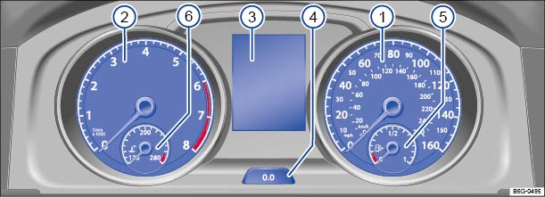 Fig. 10 Instrument cluster in the instrument panel (Golf models).
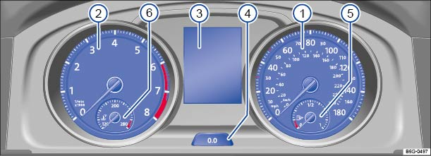 Fig. 11 Instrument cluster in the instrument panel (Golf GTI, Golf R models).Read and follow the introductory information and safety information first⇒Introduction to the subject
Instrument explanations ⇒ Fig. 10 or ⇒ Fig. 11 :
Speedometer.Tachometer (thousands of revolutions per minute when the engine is running).
The red zone at the end of the scale indicates maximum permissible engine rpm (revolutions per minute) for all gears after the break-in period. Before reaching the red zone, select the next higher gear or selector lever position D/S, or ease your foot off the accelerator ⇒ .
Displays⇒ Displays .Reset, set, and display button⇒ Displays .
Fuel gauge⇒ Refueling .Engine coolant temperature gauge Note
Upshifting early into the next higher gear saves fuel and reduces engine noise.
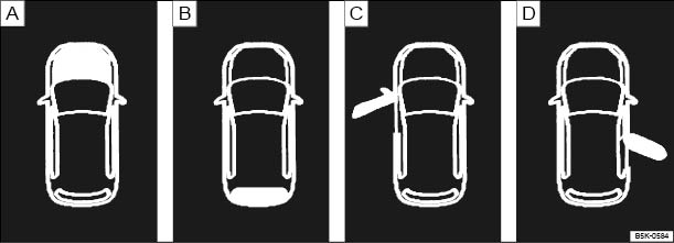 Fig. 12 In the instrument cluster display (black and white version): : Open engine hood, : Open trunk lid, : Open front driver side door, : Open rear passenger side door.
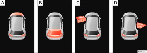 Fig. 13 In the instrument cluster display (color version): : Open engine hood, : Open trunk lid, : Open front driver side door, : Open rear passenger side door.Read and follow the introductory information and safety information first⇒Introduction to the subject
Depending on vehicle equipment, different information may be shown in the instrument cluster display.
The instrument cluster display indicates if any doors, the engine hood, or trunk lid are open once the vehicle has been unlocked, and while the vehicle is in motion. There may also be an audible warning chime. Different models and equipment versions may have different displays.
| Key to ⇒ Fig. 12 | |
|---|---|
|
|
The engine hood is open or not properly closed ⇒ Working in the engine compartment . |
|
|
The trunk lid is open or not properly closed ⇒ Trunk lid . |
|
|
One or more vehicle doors open or not properly closed ⇒ Doors . |
The status of various vehicle functions and components is monitored when the ignition is switched on and while driving. Malfunctions are indicated by red and yellow warning symbols with text messages in the instrument cluster display (⇒ Warning and indicator lights ). In some cases, they may also be signaled acoustically. The display can vary depending on the instrument cluster model.
| Type of notification | Symbol color | Explanation |
|---|---|---|
| Priority 1 warning message | Red |
Symbol flashing or lit – sometimes with acoustic warnings. . Check malfunction and take corrective action. Contact an authorized Volkswagen dealer or an authorized Volkswagen Service Facility for assistance if necessary. Menus cannot be accessed when a priority 1 warning message is displayed. The warning message will turn off automatically after a few seconds. You can confirm and turn off some warning messages by pressing the |
| Priority 2 warning message | Yellow |
Symbol flashing or continuously lit – sometimes with acoustic warnings. Malfunctions or low operating fluid levels may cause vehicle damage and vehicle breakdown ⇒ . Check malfunction as soon as possible. Contact an authorized Volkswagen dealer or an authorized Volkswagen Service Facility for assistance if necessary. |
| Information text | – | Information about various vehicle situations. |
The odometer at the bottom left corner of the instrument cluster display indicates the total distance driven by the vehicle.
The trip odometer (trip) shows the distance driven since the last time the trip odometer was reset. The last digit indicates 1/10 mile (or 100 meters, depending on the units selected).
Press the button in the instrument cluster briefly ⇒ Instrument overview to reset the trip odometer to 0.
On appropriately equipped vehicles, you can also set the time in the Infotainment system when the ignition is switched on by pressing the button followed by the
and Time and date function keys ⇒ Menu and system settings .
At outside temperatures below about +39 °F (+4 °C), a snowflake symbol appears in the display. The symbol remains on until the outside temperature rises above +43 °F (+6 °C) ⇒
.
When the vehicle is not moving or when you are driving at very low speeds, the temperature displayed may be slightly higher than the actual outside temperature.
The measurement range is from -49 °F (-45 °C) to +169 °F (+76 ℃).
On vehicles equipped with compass display, the current compass direction is indicated in the instrument cluster display when the ignition (or the navigation system, if equipped) is switched on.
The selector lever position is shown both on the side of the selector lever and in the instrument cluster display. The respective gear may be shown in the instrument cluster display in Tiptronic mode ⇒ Shifting .
When the vehicle is moving, a fuel economy gear recommendation may appear in the instrument cluster display ⇒ Shifting .
A display in the instrument cluster indicates when the set maximum speed has been exceeded ⇒ Volkswagen Information System .
On appropriately equipped vehicles, the speed warning can also be set and changed in the Infotainment system when the ignition is switched on by pressing the button followed by the
and Tires function keys ⇒ Menu and system settings .
Press and hold the button in the instrument cluster ⇒ Instrument overview for about 15 seconds to display the vehicle's engine identification code. You must do this when the doors are closed, the ignition is on, but the engine is not running.
WarningFailure to heed warning lights and instrument cluster text messages can cause the vehicle to break down in traffic and result in a collision and serious personal injury.
WarningRoads and bridges may be dangerously icy even if the outside air temperature is above freezing.
NoteFailure to heed warning lights or text WARNINGS can result in vehicle damage.The instrument cluster displays and their arrangement may vary depending on the vehicle model and engine. For displays without warning and information messages, malfunctions are only signaled with indicator lights.Depending on vehicle equipment, some settings and displays may also appear in the Infotainment system.If there are multiple warning messages, the symbols are displayed for several seconds in order of importance. The symbols are displayed until the cause has been corrected.If warning messages are displayed when the ignition is switched on, it may not be possible to adjust some settings as described, or the information display may appear differently. If this happens, take the vehicle to an authorized Volkswagen dealer or an authorized Volkswagen Service Facility for assistance.
Displayed in color on an instrument cluster with color display.
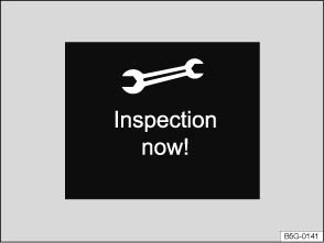 Fig. 14 In the instrument cluster display: Example of the service reminder when a service is due.
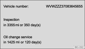 Fig. 15 In the Infotainment system display: Example of the service reminder.Read and follow the introductory information and safety information first⇒Introduction to the subject
The maintenance service reminder is shown in the instrument cluster display ⇒ Fig. 14 and in the Infotainment system ⇒ Fig. 15 . Versions and displays can vary depending on the instrument cluster or the Infotainment system version equipped with the vehicle.
For information on maintenance intervals, please see the ⇒BookletWarranty and Maintenance,.
For vehicles with time- or distance driven-dependent service, only fixed service intervals are displayed.
If service is due in the near future, a service reminder is displayed when the ignition is switched on.
The number of miles (km) or amount of time shown correspond to the maximum number of miles (km) or maximum time that can still be driven before the next service.
For a scheduled oil service or a scheduled inspection there is an audible chime when the ignition is switched on. The wrench symbol also appears for several seconds in the instrument cluster display along with one of the following messages ⇒ Fig. 14 :
| Oil service now! | |
| Inspection now! | |
| Oil service and inspection now! |
The current service message can be accessed when the ignition is switched on and the vehicle is stopped:
You can also view service information ⇒ Fig. 15 in the Infotainment system by pressing the button followed by the
and Service function keys ⇒ Menu and system settings .
If the service was not performed by an authorized Volkswagen dealer or an authorized Volkswagen Service Facility, the service reminder can be reset as follows:
| Reset oil change interval? | |
| Reset inspection interval? |
Do not reset the service reminder between service intervals; otherwise, incorrect information will be displayed.
Introduction to the subjectIn this chapter you will find information on the following subjects:⇒ Using the instrument cluster menus ⇒ Driver assistance systems button ⇒ Menu structure – overview ⇒ Main menu ⇒ Driving data ⇒ Assist systems menu ⇒ Lap timer
When the ignition is switched on, you can display different types of information in the instrument cluster and control certain vehicle features.
Your vehicle is equipped with controls either on the windshield wiper lever ⇒ Fig. 16 or steering wheel ⇒ Fig. 17 . Vehicles equipped with a multi-function steering wheel do not have buttons on the windshield wiper lever to control the displays. Vehicles equipped with controls on the windshield wiper lever are not equipped with controls on the steering wheel.
The number of menus and information in the instrument cluster display depends on the electronics and equipment on the vehicle.
An authorized Volkswagen dealer or an authorized Volkswagen Service Facility may be able to add or modify functions depending on your vehicle's equipment.
As long as a priority 1 warning message is displayed, no menus can be accessed. To display menus, acknowledge the warning by pressing the button on the windshield wiper lever ⇒ Fig. 16 or the
button on the multi-function steering wheel ⇒ Fig. 17 .
WarningDriving on today's roads demands the full attention of the driver at all times. Driver distraction causes accidents, collisions and serious personal injury!
Emergency starting and starting the engine with a very weak vehicle battery or after the vehicle battery has been replaced may change or delete system settings (including time, date, and programming). Check the settings and correct as necessary once the vehicle battery has built up a sufficient charge.
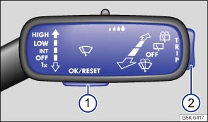 Fig. 16 On the right side of the steering column (vehicles without a multi-function steering wheel): Windshield wiper lever with controls for instrument cluster menus and displays.
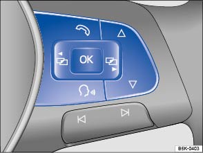 Fig. 17 Right side of the multi-function steering wheel (if equipped): Controls for the menus and information in the instrument cluster display.Read and follow the introductory information and safety information first⇒Introduction to the subject
If your vehicle does not have a multi-function steering wheel with menu controls, the instrument cluster menus are controlled with buttons on the windshield wiper lever (⇒ Fig. 16 ). On vehicles with a multi-function steering wheel, the instrument cluster menus are controlled with buttons on the right side of the steering wheel (⇒ Fig. 17 ).
To open the menu or information display shown in the selection menu, press the button on the windshield wiper lever or the
button on the multi-function steering wheel, or wait until the menu or information display opens automatically after a few seconds.
If warning messages are displayed when the ignition is switched on, it may not be possible to adjust some settings as described, or the information display may appear differently. If this is the case, take the vehicle to an authorized Volkswagen dealer or an authorized Volkswagen Service Facility for assistance.
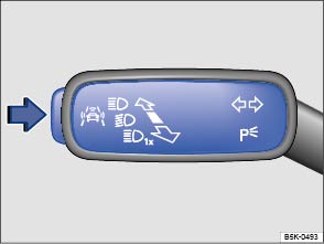 Fig. 18 On the turn signal and high beam lever: Driver assistance systems button.Read and follow the introductory information and safety information first⇒Introduction to the subject
Your vehicle may have a driver assistance systems button, which allows you to switch the driver assistance systems on or off in the Assist systems menu using the button on the turn signal lever.
On appropriately equipped vehicles, you can switch driver assist systems on and off in the infotainment system by pressing the button followed by the
and Driver Assist function keys ⇒ Menu and system settings .
Read and follow the introductory information and safety information first⇒Introduction to the subject
The following list shows how the Volkswagen information system menus in the instrument cluster display are structured. The size and layout of the Volkswagen information system menu depends on the vehicle electronics and the vehicle equipment.
Read and follow the introductory information and safety information first⇒Introduction to the subject
| Main menu | Function | See |
|---|---|---|
| Driving data | Multifunction Display (MFD) information and settings. | ⇒ Driving data |
| Display of current warning or information messages and other system components depending on the equipment level. | ⇒ Menu and system settings | |
| Assist systems | Turn selected driver assistance systems on or off, or view current status for active driver assistance systems. | ⇒ Assist systems menu |
| Compass | Current driving direction (vehicles without navigation system). | ⇒ Displays |
| Navigation | Information displays for the navigation system (if equipped). | ⇒BookletInfotainment System, |
| When route guidance is active, turn arrows and proximity bars similar to the symbols shown in the navigation system are displayed. | ||
| If route guidance is turned off, the direction of travel (compass) and the current street name are displayed. | ||
| Audio | Station display or station list in radio mode. | ⇒BookletInfotainment System, |
| Track display in media mode. | ||
| Telephone | Information about the connected telephone. | ⇒BookletInfotainment System, |
| Settings and information when using the telephone. | ||
| Vehicle status | Current warning and information messages. | ⇒ Instrument cluster |
| This menu item only appears when warning or information messages are available. | ||
| Lap timer | Time your own laps on a track, store the data, and compare with previous best times. | ⇒ Lap timer |
Read and follow the introductory information and safety information first⇒Introduction to the subject
When the ignition is on, the Driving data menu provides a variety of travel and fuel consumption data. Navigate through the data as described on ⇒ Using the instrument cluster menus .
The display has 3 automatic memories:
The currently selected memory is shown in the display.
The trip memories are in addition to the trip odometer, which is displayed in the bottom part of the instrument cluster and controlled using the .
button ⇒ Fig. 10④ or ⇒ Fig. 11④ .
Press the button on the windshield wiper lever or the
button on the multi-function steering wheel to toggle between the 3 memories when the ignition is on.
On appropriately equipped vehicles, the driving data for the trip memories can also be viewed in the Infotainment system by pressing the button followed by the Selection function key ⇒ Menu and system settings .
| 1 | Since start | The memory accumulates and stores information about distance driven and fuel used from the time the ignition was switched on until the time it was switched off. |
| If the ignition stays off for 2 hours or more, stored information is automatically deleted. If the trip is continued within 2 hours after the ignition was switched off, the new values are added. | ||
| 2 | Extend. period | Depending on the instrument cluster version, the memory displays and stores the accumulated driving and fuel consumption data of any number of single trips up to a total driving time of either 19 hours and 59 minutes 99 hours and 59 minutes, and up to a total distance of either 1,999 km or 9,999 km. If one of the maximum values is exceeded, then the memory is automatically cleared and starts again from 0. |
| 3 | Since refuel | The memory accumulates and stores information about distance driven and fuel used from the time the vehicle is refueled. The memory is deleted automatically during refueling. |
On appropriately equipped vehicles, you can set which displays should appear in the instrument cluster by pressing the button followed by the
and Instrument cluster function keys in the Infotainment system ⇒ Menu and system settings . The units in which data is displayed can also be changed.
| Display | Function |
|---|---|
| Travel time | Driving time in hours (h) and minutes (min) corresponding to trip memories 1, 2, and 3 (toggle). |
| Energy consumers | Displays any convenience equipment in the vehicle that is currently affecting fuel consumption in gallons per hour (or liters per hour). |
| Eco tips | Displays tips for better fuel economy. |
|
Range |
Estimated distance in miles (km) that the vehicle can go with the fuel left in the tank the way you are currently driving. Takes account of the current fuel consumption, among other things. |
|
Range |
|
|
--.- mpg |
Average fuel consumption in miles per gallon (l/100 km) on trips per trip memories 1, 2, and 3 (toggle). For the since start trip memory, the value is displayed once the vehicle has been driven about 330 feet (100 m). Until then, dashes appear instead of a number. The value displayed is updated every second. |
|
--.- l/100km |
|
|
Economy --.- mpg |
Current fuel consumption in miles per gallon (l/100 km) while driving. When units are set to miles, dashes appear instead of a number when the engine is running and the vehicle is standing still. When units are set to kilometers, the display shows liters consumed per hour when the engine is running and the vehicle is standing still. |
|
Economy --.- l/100km |
|
| Oil temperature --- °F | Digital display of the current engine oil temperature. |
| Oil temperature --- °C | |
|
Warning at --- mph |
When the set speed (from 20–160 mph or 30–250 km/h) is exceeded, an acoustic warning sounds and a visual message may also appear in the instrument cluster display. |
|
Warning at --- km/h |
|
|
Speed --- mph |
Digital display of the current vehicle speed. |
|
Speed --- km/h |
|
|
-- mph |
Average speed on trips per trip memories 1, 2, and 3 (toggle). For the since start trip memory, the value is displayed once the vehicle has been driven about 300 feet (100 m). The value displayed is updated every 5 seconds. |
|
-- km/h |
|
| Distance --- mi | Distance driven in miles (km) per trip memories 1, 2, and 3 (toggle). |
| Distance --- km |
May differ depending on the instrument cluster version.
Read and follow the introductory information and safety information first⇒Introduction to the subject
| Assist systems menu | Function |
|---|---|
| Lane Assist | Switch the Lane Assist system on or off (if equipped) ⇒ Lane Keeping System (Lane Assist) . |
| Blind Spot | Switch the Blind Spot monitor on or off (if equipped) ⇒ Blind Spot Monitor with Rear Traffic Alert . |
| Rear Traffic | Switch the Rear Traffic Alert on or off (if equipped) ⇒ Blind Spot Monitor with Rear Traffic Alert . |
| Front Assist | Switch the Front Assist system on or off (if equipped) ⇒ Forward Collision Warning (Front Assist) . |
Read and follow the introductory information and safety information first⇒Introduction to the subject
Your vehicle may be equipped with a lap timer that you can control via the main menu in the instrument cluster ⇒ Using the instrument cluster menus .
With the lap timer, you can time your own laps manually, store lap times, and compare the times to one another.
The following menus can be displayed:
| Menu | Submenu | Function |
|---|---|---|
| Lap timer | Start |
Timing starts. If laps have already been completed and are recorded in the statistics, timing will start from the next lap. A new first lap can only be started if the statistics are reset in the Statistics menu. |
| Since start |
Timing starts when the vehicle begins driving. If the vehicle is already in motion, timing will begin after the vehicle has come to a temporary stop. |
|
| Statistics | Statistics display in the menu. | |
| Lap 1 (or current lap number) | Stop | Active timing is interrupted. This will not end the lap. |
| New lap | Timing of the current lap is interrupted and a new lap begins. The time of the completed lap is carried over to the statistics. | |
| Split time | A split time displays for about 5 seconds. Active timing continues in parallel. | |
| Resume | Paused timing resumes. | |
| Stop lap | Timing of the active lap ends and the lap is deleted. It is not entered into the statistics. | |
| End | Active timing stops. The lap is automatically entered into the statistics. | |
| Statistics | – |
Overview of lap times most recently recorded: – Fastest time – Slowest time – Average – Total time |
| – |
A maximum of 99 laps and a maximum overall duration of 99 hours, 59 minutes, and 59 seconds can be recorded. If one of the two limits is reached, timing can only start again after the statistics are reset. |
|
| Back | Go back to the previous menu. | |
| Reset | All stored statistics data is reset. |
WarningDriving on today's roads demands the full attention of the driver at all times. Driver distraction causes accidents, collisions and serious personal injury!
WarningRapid acceleration can cause skidding and loss of traction, especially on slippery roads, resulting in a loss of vehicle control, collisions, and serious personal injury.
NoteTo help prevent engine damage, always avoid high engine speeds, full throttle acceleration, and heavy engine loads when the engine is cold.
Introduction to the subjectIn this chapter you will find information on the following subjects:⇒ Vehicle settings menu
The following section contains information on the settings that can be adjusted in the Vehicle settings menu. You can find information on operating the Infotainment system as well as warning and safety instructions in a separate manual. See ⇒BookletInfotainment System,.
After pressing the Infotainment button, you can tap the corresponding function key on the Infotainment screen to display information or adjust the following settings:
WarningDriving on today's roads demands the full attention of the driver at all times. Driver distraction causes accidents, collisions and serious personal injury!
After starting the engine with a discharged vehicle battery, or after the battery has been changed, system settings (time, date, and programming) may have been changed or deleted. Check and correct the settings as necessary once the vehicle battery has been sufficiently charged.
Read and follow the introductory information and safety information first⇒Introduction to the subject
If the box in the function key is checked , the respective function is switched on.
Changes made in settings menus are automatically applied immediately after entry.
Tapping the function key takes you back to the previous menu.
The following menu overview is an example of the Infotainment system menu structure. The size and layout of the Volkswagen information system menu depends on the vehicle electronics and the level of vehicle equipment.
| Menu | Submenu | Setting options | See |
|---|---|---|---|
| ESC system | – |
Turn the following systems on or off: – Anti-slip regulation (ASR) – ESC sport mode (ESC Sport) – ESC off (Golf R only) |
⇒ Braking and parking |
| Tires | Tire Pressure Monitoring System | Store the tire pressures (SET) | ⇒ Tire Pressure Monitoring System (TPMS) |
| Winter tires | Turn the speed warning on or off | ⇒ Tires and wheels | |
| Set the speed warning | |||
| Lights | Light Assist |
Turn the following systems on or off (if equipped): – Light Assist – Adaptive front lighting (AFS) – Automatic headlights during rain (headlights turn on with the rain sensor when the headlight switch is in – Convenience indicating (lane change feature) |
⇒ Lights |
|
Adjust the following feature (if equipped): – Turn-on time for automatic headlights ( |
|||
| Interior lighting |
Adjust the following features (if equipped): – Door ambient lighting – Footwell lighting |
||
| Coming/Leaving home function |
Set the following (if equipped): – Duration that the Coming Home feature is switched on – Duration that the Leaving Home feature is switched on |
||
| Assistance systems | ACC (adaptive cruise control) | Adjust the distance or save last distance selected (if equipped) | ⇒ Adaptive Cruise Control (ACC) |
| Front Assist (Forward Collision Warning) |
Turn the following features on or off (if equipped): – Front Assist – Advance warning – Display distance warning |
⇒ Forward Collision Warning (Front Assist) | |
| Adjust the warning period for the advance warning (Early, Medium, Late) | |||
| Lane Assist | Turn Lane Assist on or off (if equipped) | ⇒ Lane Keeping System (Lane Assist) | |
| Blind Spot Monitor | Turn the Blind Spot Monitor on or off (if equipped) | ⇒ Blind Spot Monitor with Rear Traffic Alert | |
| Parking and maneuvering | ParkPilot | Turn automatic ParkPilot (PDC) activation on or off (if equipped) | ⇒ Park Distance Control (PDC) |
|
Adjust the following: – Front volume – Front pitch – Rear volume – Rear pitch – Audio volume lowering |
|||
| Rear Traffic Alert | Turn the Rear Traffic Alert on or off (if equipped) | ⇒ Blind Spot Monitor with Rear Traffic Alert | |
| Mirrors and wipers | Mirrors |
Turn the following features on or off: – Synchronous mirror adjustment (if equipped) – Passenger side mirror lowering in reverse gear (if equipped) |
⇒ Mirrors |
| Windshield wipers |
Turn the following features on or off: – Automatic wiping during rain (rain sensor) – Wipe rear window in reverse gear |
⇒ Windshield wipers and washer | |
| Opening and closing | Window operation | Turn the convenience opening feature for the power windows on or off (if equipped) | ⇒ Power windows |
| Central locking | Set door unlocking | ⇒ Power locking system | |
|
Turn the following features on or off: – Lock automatically (Auto lock feature) – Acoustic confirmation (horn beep after the vehicle is locked from outside) |
|||
| Instrument cluster | – |
Display or hide the following data in the Multifunction display: – Current economy (fuel consumption) – Average economy (fuel consumption) – Energy consumers – Eco tips – Travel time – Distance traveled – Average speed – Digital speed display – Speed warning – Oil temperature |
⇒ Volkswagen Information System |
| – |
Reset the following data in the Multifunction display: – Driving data for Since start trip memory – Driving data for Extended period trip memory |
||
| Time and date | – |
Select and set the following data: – Clock time source (manual, GPS) – Time – Daylight savings time – Time zone – Time format (12 hour, 24 hour) – Date – Date format |
– |
| Units | – |
Set the units for the following: – Distance – Speed – Temperature – Volume – Economy (fuel consumption) – Pressure |
– |
| Service | – |
Display the following data: – Vehicle identification number (VIN) – Number of miles (km) and days until next inspection service is due – Number of miles (km) and days until next oil change service is due |
⇒ Instrument cluster |
| Factory settings | – |
Reset the following features: – All settings – Lights – Assistance systems – Parking and maneuvering – Mirrors and wipers – Opening and closing – Instrument cluster |
– |
Introduction to the subjectIn this chapter you will find information on the following subjects:⇒ Volkswagen Car-Net Security and Service ⇒ Features ⇒ Application software (“apps”) ⇒ 3-button module
Volkswagen Car-Net services are provided by Verizon Telematics, Inc. (VzT) and are available only on select models. Automatic Crash Notification (ACN) may be engaged for up to 6 months without activating a trial or paid subscription; Manual Emergency Call service and all other Volkswagen Car-Net services require a trial or paid subscription. Volkswagen Car-Net may collect location information. See applicable Terms of Service and Privacy Policy available at www.vw.com/carnet for details.
Vehicle location information is transmitted to Volkswagen and our Volkswagen Car-Net service provider, Verizon Telematics, Inc. (VzT), anytime you press a Volkswagen Car-Net in-car button, when an ACN event occurs or periodically in connection with the operation of Volkswagen Car-Net.
Unless Volkswagen Car-Net equipment is disabled in the vehicle, it is possible for Volkswagen and VzT to determine the car’s location if required to do so by law, court order, subpoena or other legal requirement. For more information, please contact the Volkswagen Car-Net Response Center at 1-877-820-2290.
Calls may be monitored or recorded.
Volkswagen collects, processes, transmits, uses, and shares information about you and your vehicle in accordance with the Volkswagen Car-Net Terms of Service and Privacy Policy. See the Volkswagen Car-Net Terms of Service and Privacy Policy at (http://www.vw.com/carnet) for more details.
WarningApplication software and Volkswagen Car-Net services that are unsuitable or improperly used can cause accidents, serious personal injury and vehicle damage.
WarningDriver distraction causes accidents, collisions and serious personal injury! Using application software and Volkswagen Car-Net services while driving can distract the driver from traffic.
Read and follow the introductory information and safety information first⇒Introduction to the subject
Your vehicle has equipment to enable Volkswagen Car-Net, a suite of connected vehicle services that makes driving and owning a Volkswagen vehicle more convenient. Volkswagen Car-Net allows you to seamlessly connect your car and your life by offering the following services:
You can access Volkswagen Car-Net Security and Service via your Volkswagen Car-Net iPhone or Android app (text and data rates apply) and the Volkswagen Car-Net Security and Service website (http://www.vw.com/carnet). If you have a question or would like to subscribe, please either press the ⇒ Fig. 21① or ⇒ Fig. 22① button in your vehicle or contact the Volkswagen Car-Net Response Center at 1-877-820-2290. For more information or to log on to your Volkswagen Car-Net Security and Service account, visit http://www.vw.com/carnet.
Note: Please review the Volkswagen Car-Net Security and Service Terms of Service and Privacy Policy at http://www.vw.com/carnet.
Automatic Crash Notification (ACN) may be engaged for up to 6 months, starting from the date of new vehicle sale, without activating a trial or paid subscription.
The Manual Emergency Call service and all other Volkswagen Car-Net Security and Service features require a trial or paid subscription. To begin your trial or paid subscription, authentication and activation are required. For more information, please visit the website (http://www.vw.com/carnet), press the ⇒ Fig. 21① or ⇒ Fig. 22① button in the 3-button module in your vehicle or contact the Volkswagen Car-Net Response Center at 1-877-820-2290.
The LED light in the 3-button module will be green during the trial period and whenever you have an active subscription. The LED light will go off if the trial period is over and the customer has not subscribed to the Volkswagen Car-Net services. The LED light will be red only during a VW Car-Net hardware malfunction or fault ⇒ 3-button module .
Once a trial or paid Volkswagen Car-Net Security and Service subscription has been activated, please advise all who use the vehicle that different kinds of data can be sent and received automatically by the vehicle, including speed, location and more.
WarningVehicle health reports do not replace the information provided by the vehicle warning and indicator lights. Failure to heed warning lights and instrument cluster text messages can cause the vehicle to break down in traffic and result in a collision and serious personal injury.
NoteFailure to heed warning lights or text WARNINGS can result in vehicle damage.Volkswagen collects, processes, transmits, uses and shares information about you and your vehicle in accordance with the Volkswagen Car-Net Terms of Service and Privacy Policy. See the Volkswagen Car-Net Security and Service Terms of Service and Privacy Policy at http://www.vw.com/carnet for more details.Volkswagen Car-Net Security and Service services use a system based on a wireless communication network. If all technical and other conditions are met and Volkswagen Car-Net Security and Service still does not work properly, please try using the service again later.
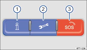 Fig. 19 In the roof console: 3-button module to access Volkswagen Car-Net service operators (Version 1).
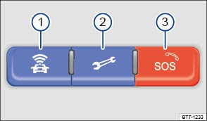 Fig. 20 In the roof console: 3-button module to access Volkswagen Car-Net service operators (Version 2).Read and follow the introductory information and safety information first⇒Introduction to the subject
The following listed features are available after Volkswagen Car-Net Security and Service registration either through the 3-button module ⇒ 3-button module , a mobile device ⇒ Application software (“apps”) , the Volkswagen Car-Net Security and Service website (http://www.vw.com/carnet) or by contacting the Volkswagen Car-Net Response Center at 1-877-820-2290. They are divided into 4 categories: Safe & Secure, Family Guardian, Remote Vehicle Access and Diagnostics & Maintenance Services. Always refer to the Volkswagen Car-Net Security and Service website for the most up-to-date information regarding Volkswagen Car-Net Security and Service services.
| Safe & Secure: | ||
|---|---|---|
| Feature | Description | |
| Automatic Crash Notification (ACN) | Automatic Crash Notification is initiated in the event of airbag deployment or rollover. When the feature is activated the Volkswagen Car-Net Response Center is notified of your location and contacts your vehicle to determine the risk of injury and to dispatch help. Help is dispatched even if the Volkswagen Car-Net Response Center does not connect to the vehicle's occupants. Automatic Crash Notification may be engaged for up to 6 months without activating a trial or paid subscription. | |
| Manual Emergency Call | In the case of an emergency, press the button ③ in the 3-button module: The Volkswagen Car-Net device initiates a connection to the Volkswagen Car-Net Response Center. The location of the vehicle and customer data for identification is sent at the same time. | |
| Roadside Assistance | Press the button ② in the 3-button module: The vehicle will connect directly to the Volkswagen Roadside Assistance Call Center. The vehicle’s location is also transmitted in order to more quickly provide assistance. | |
|
Stolen Vehicle Location Assistance For use by law enforcement authorities only. See Terms of Service at www.vw.com/carnet for details. |
After you have reported your vehicle as stolen to law enforcement, you may provide the case information to the Volkswagen Car-Net Response Center. Once the information has been verified, the VW Car-Net Customer Specialist will be able to provide law enforcement with vehicle location data sent by the VW Car-Net module. | |
| Family Guardian: | ||
|---|---|---|
| Feature | Description | |
| Boundary Alert | By logging on to your Volkswagen Car-Net Security and Service account, you can designate an area on a map as a “virtual fence.” The vehicle owner can then choose notification channels (text message or email) for receiving alerts when the vehicle crosses the defined boundary (texts and data rates apply). | |
| Speed Alert | Volkswagen Car-Net Security and Service can be configured to inform the vehicle owner whenever the vehicle exceeds a speed set by the owner. The owner can select to be informed through multiple channels, including text messages and email (text and data rates apply). | |
| Remote Vehicle Access: | ||
|---|---|---|
| Feature | Description | |
| Remote Door Unlock | You can send a request to unlock the vehicle doors through your Volkswagen Car-Net iPhone or Android app, the Volkswagen Car-Net Security and Service website or by calling the Volkswagen Car-Net Response Center (text and data rates apply). If none of the vehicle doors are opened within about 30 seconds, the car will lock again. | |
| Remote Door Lock | You can send a request to lock the vehicle doors through your Volkswagen Car-Net iPhone or Android mobile application, the Volkswagen Security and Service website or by calling the Volkswagen Car-Net Response Center (text and data rates apply). | |
| Remote Honk and Flash | You can send a honk and flash signal to the car using the Volkswagen Car-Net Security and Service website or the VW Car-Net iPhone or Android app (text and data rates apply). The car will honk the horn and blink the headlights and emergency flashers for up to 10 seconds. | |
| Last Parked Location | You can locate your last parked location using your Volkswagen Car-Net iPhone or Android app (text and data rates apply). | |
|
Destinations Only applicable for vehicles equipped with a factory-installed navigation system. |
Points of Interest (POIs) or other destinations can be imported remotely into the factory-installed navigation system (if equipped) from a computer or the Volkswagen Car-Net iPhone or Android app (text and data rates apply). These destinations can be called up and used by the navigation system. | |
|
Destination Download Only applicable for vehicles equipped with a factory-installed navigation system. |
Press the button ① in the 3-button module: The vehicle will connect directly to the Volkswagen Car-Net Response Center where a Volkswagen Car-Net Customer Specialist will assist with destinations. The address of a dealer’s location can also be sent by the Customer Specialist to your factory-installed navigation system (if equipped). | |
| Remote Status Check | Current information about the vehicle can be viewed through a computer or your Volkswagen Car-Net iPhone or Android app (text and data rates apply). You can find out if the doors, luggage compartment and engine hood are open or closed, whether the car lights are on or off, the level of fuel in the tank, when the vehicle needs to be serviced next and more. | |
| Diagnostics & Maintenance: | ||
|---|---|---|
| Feature | Description | |
| Dealer Scheduling | Press the button ① in the 3-button module: The vehicle will initiate a call to the Volkswagen Car-Net Response Center where a Volkswagen Car-Net Customer Specialist will connect you with an authorized Volkswagen dealer to schedule your service appointment. The address of the dealer’s location can also be sent by the Customer Specialist to your factory-installed navigation system (if equipped). | |
| Vehicle Health Report | View a vehicle health report to proactively manage maintenance and other services and to receive up-to-date diagnostics in a monthly email report or by immediate request. | |
WarningRefer to your vehicle's warning and indicator lights for the most current diagnostic information. Always consult this manual for maintenance guidelines. Failure to heed warning lights and instrument cluster text messages can cause the vehicle to break down in traffic and result in a collision and serious personal injury.
The Volkswagen Car-Net Security and Service website (http:// www.vw.com/carnet) contains the most up-to-date information and instructions about Volkswagen Car-Net Security and Service services.
Read and follow the introductory information and safety information first⇒Introduction to the subject
Many mobile devices are equipped to load application software (apps) into the device. Apps can make it possible to display additional information on the factory-installed Radio or Navigation system or activate, control or deactivate specific vehicle features.
Application software, its usage and the wireless connection required to use application software may be billable services. Apps may be provided by third parties. Therefore you should refer to the terms of use and privacy statements associated with the apps for information about how the apps collect, use and share information about you, your vehicle or your mobile device.
The application software provided may be designed to be used for a variety of purposes and be specific to your vehicle and country ⇒ . The content, range of software provided and application software provider can vary. Some application software is also subject to the availability of services provided by third parties. In order for some application software to work, wireless service reception must be strong enough to handle the data exchange involved (text and data rates apply).
Application software descriptions may be provided by the service provider.
Due to the multitude of mobile devices and fast pace of software development, the application software provided may not run on all mobile devices and their operating systems. This may even apply for the same model of a mobile device. For example, application software may run on version 2 of the device's operating system but not on version 3.
Application software can be modified, discontinued, deactivated, reactivated or expanded without any further notice.
In order for some application software to work, the wireless or cable connection between the factory-installed Radio or Navigation system and a compatible, functioning mobile device must be strong enough and uninterrupted.
NoteVolkswagen is not responsible for vehicle damage caused by inferior-quality or malicious application software, poorly programmed application software, insufficient wireless service reception, data loss during transmission or misuse of mobile devices.
Fig. 21 In the roof console: 3-button module to access Volkswagen Car-Net service operators (Version 1).Fig. 22 In the roof console: 3-button module to access Volkswagen Car-Net service operators (Version 2).Read and follow the introductory information and safety information first⇒Introduction to the subject
The buttons in the 3-button module provide access to several Volkswagen Car-Net Security and Service features and pressing a button will initiate a connection to the Volkswagen Car-Net Response Center. Calls may be monitored or recorded. In general, the Volkswagen Car-Net Customer Specialist will end the call.
| ⇒ Fig. 21 or ⇒ Fig. 22 | Function |
|---|---|
| ① |
Press and hold for longer than 2 seconds: Connects to the Volkswagen Car-Net Response Center and a Volkswagen Car-Net Customer Specialist. Press again: End the call. |
| ② |
Press and hold for longer than 2 seconds: Assistance in the event of a breakdown by connecting to the Volkswagen Roadside Provider. Press again: End the call. |
| ③ |
Press and hold for longer than 2 seconds: Activate emergency call. Press again: End the call. |
The LED light in the 3-button module will be green during the trial period and whenever you have an active subscription. The LED light will go off if the trial period is over and the customer has not subscribed to the Volkswagen Car-Net Security and Service. The LED light will be red only during a VW Car-Net hardware malfunction or fault.
WarningApplication software and Volkswagen Car-Net Security and Service services that are unsuitable or improperly used can cause accidents, serious personal injury and vehicle damage.
WarningDriver distraction causes accidents, collisions and serious personal injury! Using application software and Volkswagen Car-Net services while driving can distract the driver from traffic.
NoteThe system does not support simultaneous Volkswagen Car-Net Security and Service and mobile phone calls via the mobile phone package.
Introduction to the subjectIn this chapter you will find information on the following subjects:⇒ Getting ready and driving safely ⇒ Driving in other countries ⇒ Driving through water on roads WarningDriving under the influence of alcohol, illegal drugs, narcotics and some medications may cause collisions and other accidents, severe personal injuries and even death.
Read and follow the introductory information and safety information first⇒Introduction to the subject

Check proper function of lights and turn signals.
Check tire pressure (Tires and wheels) and fuel level (Refueling).
Make sure that all windows are clean.
Make sure that the engine is not covered by blankets or other materials and that the engine air intake is free of obstacles.
Store items and all luggage safely in the storage compartments, in the luggage compartment and, where applicable, on the roof Transporting.
Always make sure that nothing keeps the pedals from moving freely.
Make sure that children are properly secured by a restraint system appropriate for their size and weight Child safety and child restraints.
Properly adjust front seats, all head restraints and mirrors to the correct height Adjusting the seating position.
Wear shoes that give your feet a good grip and that give you a feel for the pedals.
Make sure that the floormat on the driver side is properly fastened and cannot interfere with the pedals.
Assume a proper seating position before the vehicle starts to move and keep this position while driving. Make sure that all passengers do the same Adjusting the seating position.
Properly fasten your safety belt before driving the vehicle and wear your safety belt properly at all times while driving. Make sure that all passengers do the same Safety belts.
Only transport as many passengers as there are seats and safety belts available.
Never drive if your driving ability has been impaired, for example, by medication, alcohol, or illegal drugs.
Never let passengers or phone calls distract you while driving and never take your attention off the road while using vehicle software or adjusting vehicle equipment or accessories.
Always adapt your speed and driving style to visibility, weather, road, and traffic conditions.
Always obey traffic laws and speed limits.
On long trips make frequent rest stops – at least once every 2 hours.
Secure animals in the vehicle with a system that corresponds to their weight and size.
WarningAlways observe traffic rules and posted speed limits and use common sense. Your good judgment can mean the difference between arriving safely at your destination and being seriously injured in a crash or other kind of accident.Regular service and maintenance of your vehicle is important both for operational and driving safety and to help prolong your vehicle's service life. Always follow the scheduled maintenance intervals in the ⇒BookletWarranty and Maintenance,, especially for changing the brake fluid. Hard use, frequent stop-and-go driving, driving in very dusty areas, trailer towing, and other factors may make it necessary to have the vehicle serviced more frequently. Ask an authorized Volkswagen dealer or an authorized Volkswagen Service Facility for more information.
Read and follow the introductory information and safety information first⇒Introduction to the subject
Should the vehicle be technically prepared for the trip abroad, such as masking or adjusting headlights?
Are maintenance, repair facilities, necessary tools, and testing equipment as well as spare parts readily available for your vehicle?
Are there authorized Volkswagen dealers and authorized Volkswagen Service Facilities in the countries where you will be driving?
Is fuel with the appropriate rating for your vehicle's engine requirements readily available Fuel?
Are engine oil (Engine oil) and other operating fluids that meet Volkswagen quality and performance requirements available where you will be driving? For more information, please see Warranty and Maintenance.
Does the factory-installed navigation system work in the countries where you will be driving, and is navigation data available?
Are special or heavy-duty tires necessary for the kind of driving expected?
NoteVolkswagen is not responsible for mechanical damage that may result from substandard fuel or service or the unavailability of Genuine Volkswagen parts.
Read and follow the introductory information and safety information first⇒Introduction to the subject
Note the following to help prevent vehicle damage when driving through water, for example on flooded roads:
.WarningAfter driving through water, mud, sludge, etc., the brakes react slower and need longer stopping distances.
Note
Introduction to the subjectIn this chapter you will find information on the following subjects:⇒ Important vehicle labels ⇒ Engine data ⇒ Dimensions
Your vehicle's engine type is shown on the vehicle identification label.
The specifications in this Manual refer to the base model. The stated values may vary, depending upon different equipment or models, as well as with respect to special vehicles and vehicles exported to different countries.
WarningDisregarding or exceeding stated values for weights, loads, dimensions and maximum speed may result in accidents and serious personal injuries.
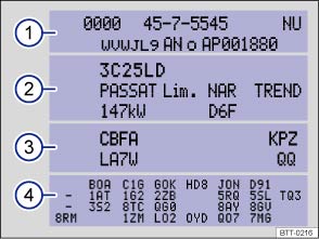 Fig. 23 Vehicle identification label: Shown in the example with engine identification code CBFA ③.
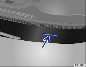 Fig. 24 Vehicle identification number (VIN).Read and follow the introductory information and safety information first⇒Introduction to the subject
Factory-installed safety certificates, stickers, and signs containing important information regarding vehicle operation can be found in the engine compartment and on certain vehicle components, such as inside the fuel filler flap, on the passenger sun visor, in the driver door jamb, or on the luggage compartment floor.
The vehicle identification number is on a plate on top of the instrument panel on the driver side, and is visible from the outside through the windshield ⇒ Fig. 24 (arrow). The view window is on the side at the bottom of the windshield. The vehicle identification number is also stamped into the top of the right drip channel in the engine compartment. The drip channel is between the spring strut tower and the right fender. Open the engine hood to read the vehicle identification number ⇒ Working in the engine compartment .
The vehicle identification number can be displayed in the Infotainment system by pressing the button followed by the
and Service function keys ⇒ Menu and system settings .
The vehicle identification label ⇒ Fig. 23 is affixed to the area of the spare wheel well underneath the luggage compartment floor panel and contains the following information:
Vehicle identification number (VIN)Vehicle type, engine output, and transmissionEngine and transmission identification codes, paint number, and interior type. In the example, the engine identification code is CBFA ⇒ Fig. 23 .Optional equipment and part numbersA safety certificate affixed to the door jamb in the driver door confirms that at time of production all necessary safety standards and requirements of the traffic safety agency of the respective country were met. The month and year of production as well as the vehicle identification number may be listed as well.
A warning sticker about the radiator fan and the high voltage of the electrical system is located in the engine compartment next to the engine hood release. The vehicle ignition system complies with the Canadian standard ICES-002.
A tire inflation pressure label is on the driver door jamb ⇒ Tires and wheels .
An information sticker listing the correct fuel grade for your vehicle ⇒ Refueling .
Read and follow the introductory information and safety information first⇒Introduction to the subject
| Maximum power output | Injection technology | Engine ID code | Maximum torque |
No. of cylinders Displacement |
|---|---|---|---|---|
|
170 hp at 4800–6200 rpm (125 kW at 4800–6200 rpm) |
TSI |
CXBA CXBB 1.8L |
184 lb-ft at 1500–4700 rpm (250 Nm at 1500–4700 rpm) |
4 cylinders 110 CID (1798 ccm) |
| Maximum power output | Injection technology | Engine ID code | Maximum torque |
No. of cylinders Displacement |
|---|---|---|---|---|
|
210 hp at 4300–6200 rpm (155 kW at 4300–6200 rpm) |
TSI |
CNTA CXCA 2.0T |
258 lb-ft at 1600–4200 rpm (350 Nm at 1600–4200 rpm) |
4 cylinder 121 CID (1984 ccm) |
|
220 hp at 4500–6200 rpm (162 kW at 4500–6200 rpm) |
TSI |
CXCB 2.0T |
258 lb-ft at 1600–4400 rpm (350 Nm at 1600–4400 rpm) |
4 cylinder 121 CID (1984 ccm) |
| Maximum power output | Injection technology | Engine ID code | Maximum torque |
No. of cylinders Displacement |
|---|---|---|---|---|
|
292 hp at 5400–6200 rpm (215 kW at 5400–6200 rpm) |
TSI |
CYFB 2.0T |
280 lb-ft at 1900–5300 rpm (380 Nm at 1900–5300 rpm) |
4 cylinder 121 CID (1984 ccm) |
Using gasoline that does not meet minimum octane requirements can cause loss of engine performance, while the use of poor quality gasoline or octane levels below 87 can also cause engine damage. If Regular gasoline is recommended for your engine, you may be able to enhance engine performance by using Premium gasoline.
Engine performance data using Premium grade gasoline ⇒ Fuel
Read and follow the introductory information and safety information first⇒Introduction to the subject
| Length | 167.5–168.3 inches (4255–4276 mm) |
| Width (2-door) | 70.5 inches (1790 mm) |
| Width (4-door) | 70.8 inches (1799 mm) |
| Height (unloaded) | 56.5–58.1 inches (1436–1477 mm) |
| Wheelbase | 103.5–104.3 inches (2631–2651 mm) |
| Minimum turning circle diameter (wall to wall) | about 36.4 feet (11.1 m) |
| Track, front | 60.1–70 inches (1527–1549 mm) |
| Track, rear | 58.9–59.8 inches (1498–1520 mm) |
| Ground clearance (unloaded) | about 4.8–5.6 inches (122–142 mm) |
Note
Slight differences to these figures are possible, depending on wheel and tire size fitted, tire inflation pressure, equipment level, driving situation, and other factors.
Introduction to the subjectIn this chapter you will find information on the following subjects:⇒ Remote control vehicle keys ⇒ Indicator light in the remote control vehicle key ⇒ Replacing the remote control vehicle key battery ⇒ Synchronizing the remote control vehicle key Danger!20 mm button cells and other lithium batteries will cause serious personal injury and even death within a short time if swallowed.
WarningImproper use of vehicle keys can result in serious personal injury.
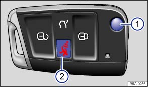 Fig. 25 Remote control vehicle key with panic button.Read and follow the introductory information and safety information first⇒Introduction to the subject
The remote control vehicle key can unlock and lock the vehicle from a distance ⇒ Power locking system .
The remote transmitter and battery are inside the remote control vehicle key. The receiver is inside the passenger compartment. The operating range of the remote control vehicle key for a fresh battery is several yards (meters) around the vehicle.
If the remote control vehicle key will not lock or unlock your vehicle, you probably need to replace the battery in the remote control vehicle key ⇒ Replacing the remote control vehicle key battery . If this is not the problem, the key should be resynchronized by an authorized Volkswagen dealer, an authorized Volkswagen Service Facility, or another qualified workshop. See also ⇒ Synchronizing the remote control vehicle key .
Pressing button ⇒ Fig. 25① releases the key bit and folds it out.
To fold the key bit in press button ① while pressing the key bit back until it clicks.
Press the panic button ⇒ Fig. 25② only in emergencies! After pushing the panic button, the horn will sound and the turn signals will flash. Press the panic button again or press the button on the remote control vehicle key to switch off the panic feature.
The vehicle identification number is required to get a replacement key or an additional remote control vehicle key.
Each new vehicle key contains a microchip and must be coded with the data from the vehicle's electronic immobilizer. A vehicle key will not work if it does not contain a microchip or contains a chip that is not coded, even if the key bit was cut correctly.
You can obtain additional or duplicate remote control vehicle keys from authorized Volkswagen dealers, authorized Volkswagen Service Facilities, and from certain independent repair facilities and locksmiths which are qualified to make remote control vehicle keys.
Each vehicle key must be programmed by an authorized Volkswagen dealer or an authorized Volkswagen Service Facility in order for it to work with your vehicle.
To find the nearest qualified independent repair facility, locksmith, or Volkswagen dealer which can cut and code replacement vehicle keys, call the VW Customer Care Hotline at 1-800-822-8987 or visit http://www.vw.com and search for replacement keys.
Canadian customers can contact an authorized Volkswagen dealer or Volkswagen Service Facility or call the Volkswagen Canada Customer CARE Center at 1-800-822-8987.
NoteThe remote control vehicle keys contain electrical components. Protect them from damage, moisture and rough handling.Do not press the buttons on the remote control vehicle key unless you actually want to use the function in question. Since terrain and conditions vary, pressing a button on the remote control vehicle key when it is not necessary may unlock the vehicle or set off the panic alarm, even if you think you are out of range.Remote control vehicle key functions can be temporarily disrupted by interference from transmitters near the vehicle that use the same frequency range (such as radio equipment or mobile phones).Things between the remote control vehicle key and vehicle, bad weather, as well as a weak battery can reduce the operating range.If the remote control vehicle key buttons ⇒ Unlocking or locking the vehicle from the outside or the power locking buttons ⇒ Unlocking or locking the vehicle from the inside are pushed repeatedly in quick succession, the power locking system is switched off for a brief period to help keep it from being overloaded. The vehicle is then unlocked for about 30 seconds. Unless a door or the trunk lid is opened in this span of time, the vehicle is automatically locked afterwards.
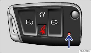 Fig. 26 Indicator light in the remote control vehicle key.Read and follow the introductory information and safety information first⇒Introduction to the subject
If a button on the remote control vehicle key is pressed briefly, the indicator light ⇒ Fig. 26 (arrow) will flash once briefly. If you push and hold a button, it flashes repeatedly.
If the indicator light in the remote control vehicle key does not come on when the button is pressed, the battery inside the key must be replaced ⇒ Replacing the remote control vehicle key battery .
A Declaration of Compliance with United States FCC and Industry Canada regulations is found in the Consumer information section of this Manual ⇒ Consumer information .
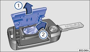 Fig. 27 Remote control vehicle key: Opening the battery compartment cover and removing the old battery.Read and follow the introductory information and safety information first⇒Introduction to the subject
Volkswagen recommends having the battery in the remote control vehicle key changed by an authorized Volkswagen dealer or an authorized Volkswagen Service Facility.
The battery is on the back of the remote control vehicle key under a cover ⇒ Fig. 27① .
When changing the battery, pay attention to the correct polarity and use the same type of battery ⇒ .
. .Note
Dispose of old batteries in an environmentally responsible manner and keep them out of the reach of children.Batteries of the type used in your remote control vehicle key may contain Perchlorate Material. Special handling may apply – see http://www.dtsc.ca.gov/hazardouswaste/perchlorate. Obey all legal requirements regarding handling and disposal of these batteries. Authorized Volkswagen dealers and authorized Volkswagen Service Facilities are familiar with the requirements, and we recommend that you have them perform this service for you.
Read and follow the introductory information and safety information first⇒Introduction to the subject
If the button is pressed often while outside the operating range, it is possible that the vehicle cannot be locked or unlocked anymore with the remote control vehicle key. Synchronize the vehicle key as follows:
Introduction to the subjectIn this chapter you will find information on the following subjects:⇒ Indicator light in the driver door ⇒ Description of the power locking system ⇒ Unlocking or locking the vehicle from the outside ⇒ Unlocking or locking the vehicle from the inside ⇒ Unlocking or locking the vehicle with Keyless Access ⇒ Anti-theft alarm system
The power locking system works properly only when all doors and the trunk lid are completely closed. When the driver door is open, the vehicle cannot be locked with the remote control vehicle key.
For vehicles equipped with Keyless Access with push-button start, the vehicle can be locked only if the ignition is switched off and the driver door is closed.
Leaving the vehicle unlocked for longer periods of non-use (for example, in your garage) can cause the vehicle battery to drain so that the engine can no longer be started.
WarningImproper use of power locks can result in serious personal injury.
Read and follow the introductory information and safety information first⇒Introduction to the subject
The indicator light for the power locking system is in the driver door ⇒ Passenger compartment .
| After the vehicle is locked | Meaning |
|---|---|
| The red LED light flashes for about 2 seconds in short intervals, then slower. | The vehicle is locked. |
| Red LED light flashes for about 2 seconds in short intervals, then lights up continuously for about 30 seconds. | Locking system malfunction. See an authorized Volkswagen dealer or an authorized Volkswagen Service Facility. |
NoteFailure to heed warning lights or text WARNINGS can result in vehicle damage.
Read and follow the introductory information and safety information first⇒Introduction to the subject
The power locking system lets you unlock and lock all doors and the trunk lid:
When the vehicle is locked from the outside, the fuel filler flap is also locked.
Certain central locking functions can be turned on and off in the Infotainment system by pressing the button followed by the
and Opening and closing function keys ⇒ Menu and system settings , or by an authorized Volkswagen dealer or authorized Volkswagen Service Facility.
The doors and the trunk lid can be locked manually if the remote control vehicle key or the power locking system is not working ⇒ Emergency closing and opening .
The vehicle locks automatically when it reaches a speed of about 10 mph (15 km/h). When the vehicle is locked, the indicator light comes on in the power locking button ⇒ Fig. 29 .
All doors automatically unlock when you switch off the ignition or open a door from inside the vehicle. On vehicles with automatic transmission, the doors will also unlock when the selector lever is in Park (P). Auto unlock works only if the vehicle has been automatically locked with the Auto lock feature. The indicator light goes out in the power locking button when the doors unlock ⇒ Fig. 29 .
If the airbags are activated during a collision, the entire vehicle is unlocked. Depending on the severity of the damage, the vehicle can be locked after a collision when the airbags have deployed as follows:
| Function | Action |
|---|---|
| Locking the vehicle with the power locking button: |
– Switch the ignition off. – Open and close a door once. – Press the power locking button |
| Locking the vehicle with the remote control vehicle key: |
– Switch the ignition off. OR: Remove the vehicle key from the ignition. – Open a door once. – Lock the vehicle with the remote control vehicle key. |
If the vehicle key buttons ⇒ Unlocking or locking the vehicle from the outside or the power locking buttons ⇒ Unlocking or locking the vehicle from the inside are pushed repeatedly in quick succession, the power locking system is switched off for a brief period to help keep it from being overloaded. The vehicle is then unlocked for about 30 seconds. Unless a door or the trunk lid is opened during this time, the vehicle is automatically locked afterwards.
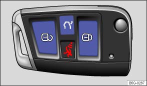 Fig. 28 Remote control vehicle key with panic button.Read and follow the introductory information and safety information first⇒Introduction to the subject
| Function | Using the buttons on the remote control vehicle key ⇒ Fig. 28 |
|---|---|
| Unlock the vehicle: |
Press the |
| Lock the vehicle: |
Press the |
| Unlock the trunk lid: |
Press the |
Note: Depending on the settings for the power locking system that have been set in the Infotainment system, it may be necessary to press the button on the remote control vehicle key twice to unlock all doors and the trunk lid ⇒ Volkswagen Information System .
The vehicle key unlocks or locks the vehicle only when the battery in the remote control vehicle key has enough power, and the remote control vehicle key is within a few yards/meters of the vehicle.
If the turn signals do not flash to confirm locking, one or more doors or the trunk lid is not locked.
If the driver door is open, the vehicle cannot be locked with the remote control vehicle key.
If the vehicle was unlocked with the remote control vehicle key and the door or the trunk lid has not been opened within several seconds, the vehicle is automatically locked again. This feature helps prevent you from leaving the vehicle unlocked unintentionally.
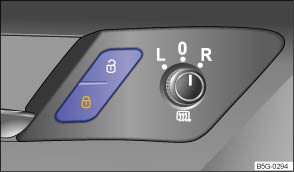 Fig. 29 In the driver and front passenger doors: Power locking button.Read and follow the introductory information and safety information first⇒Introduction to the subject
| Press button ⇒ Fig. 29 : | |
|---|---|
|
|
Unlock the vehicle. |
|
|
Lock the vehicle. |
The power locking button works whether the ignition is switched on or off but only when all doors are closed.
If the vehicle is locked with the vehicle key, the power locking button is deactivated.
If the vehicle is locked with the power locking button:
The vehicle is unlocked if you push the button while the vehicle is standing still. It also unlocks when you switch off the ignition or open a door from inside the vehicle (Auto unlock). On vehicles with automatic transmission, the doors will also unlock when the selector lever is in Park (P). Auto unlock works only if the vehicle has been automatically locked with the Auto lock feature.
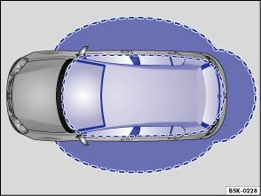 Fig. 30 Ranges of the Keyless Access system. Outside the vehicle: Unlocking range. Inside the vehicle: Starting range.
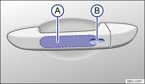 Fig. 31 Keyless Access system: Sensor for unlocking Ⓐ on the inside of the front door handles. Sensor for locking Ⓑ on the outside of the front door handles.Read and follow the introductory information and safety information first⇒Introduction to the subject
Your vehicle may be equipped with Keyless Access with push-button start, a keyless starting and locking system that unlocks and locks the vehicle without active use of a remote control vehicle key. All you have to do is touch a sensor surface on one of the front outside door handles ⇒ Fig. 31 or push the Volkswagen emblem on the trunk lid ⇒ Opening the trunk lid when a valid remote control vehicle key is within range ⇒ .
When a valid vehicle key comes within range ⇒ Fig. 30 , the Keyless Access system recognizes a valid vehicle entry request as soon as a door handle sensor is touched on the driver or front passenger door or the Volkswagen emblem on the trunk lid is pressed. The following functions are then enabled without active use of the remote control vehicle key:
The power locking system works like the standard unlocking and locking system. Only the way that the systems are operated is different.
All turn signals flash twice to confirm that the vehicle has been unlocked and once to confirm that it has been locked.
If the vehicle is unlocked and within the next several seconds no door or the trunk lid has been opened, the vehicle is automatically locked again.
To help prevent you from locking yourself out, the vehicle will not lock immediately in the following situation:
The vehicle does not fully lock. All turn signals flash four times. Take the remote control vehicle key out of the vehicle and lock the vehicle again.
The vehicle will lock again after a short time if you do not open one of the doors or the trunk lid.
If the vehicle is locked and a valid remote control vehicle key is within range ⇒ Fig. 30 of the trunk lid, it unlocks automatically when opened.
Open and close the trunk lid as you would a standard trunk lid ⇒ Trunk lid .
The trunk lid locks automatically when it is closed except in the following situations:
If the vehicle is locked from the outside with a second valid vehicle key, any key located inside the vehicle cannot start the engine ⇒ Starting and stopping the engine . A key that was inside the vehicle when it was locked from the outside can be reactivated by pressing the button on the deactivated key ⇒ Fig. 28 .
If the vehicle has not been unlocked or locked for a longer period of time, the sensors in the door handles are automatically deactivated.
If a sensor on the door handle of a locked vehicle is activated too often, for instance by a bush or hedge that rubs against the vehicle, that sensor may be switched off for a short time.
The door handle sensors become active again if one of the following events occurs:
Your vehicle may be equipped with the convenience closing feature.
To use the convenience closing feature to close all power windows and the sunroof, hold your finger on the lock sensor surface on the outside of the door handle ⇒ Fig. 31Ⓑ for a few seconds until the windows and sunroof close.
Remove your finger from the lock sensor surface to stop the function.
Pinch protection is active during convenience closing of the windows and the power sunroof.
NoteThe door handle sensor surfaces can be activated by a strong stream of water or steam if a valid vehicle key is within range of the vehicle.
The door may not open if the outside and inside door handles are used at the same time.If the vehicle battery or the battery in the remote control vehicle key is weak or dead, it might not be possible to unlock and lock the vehicle using Keyless Access. The vehicle can still be manually locked or unlocked with the key bit ⇒ Manually unlocking and locking the driver door .To help make sure that the vehicle stays locked after you press the locking sensor on the door handle, the unlocking function on that door handle is deactivated for about 2 seconds after locking the vehicle.A driver information message may appear in the instrument cluster display if there is a Keyless Access system malfunction. See an authorized Volkswagen dealer or an authorized Volkswagen Service Facility for assistance.A driver information message appears in the instrument cluster display if there is no remote control vehicle key inside the vehicle or if the system does not recognize the remote control vehicle key. The key may not be recognized, for example, if it is covered by something that interferes with the signal (such as a briefcase), or if the remote control vehicle key battery is weak. Electronic devices such as mobile phones can also interfere with the signal.Dirt on the door handles that contains a lot of salt (especially in winter) can affect the way the door handle sensors work. Cleaning the door handles can help with this problem ⇒ Exterior care and cleaning .If the automatic transmission is not in Park (P) position, the electronic steering column lock will not lock and the vehicle will not lock via sensors in the front door handles or the remote control vehicle key.By touching the unlocking sensor surface twice in a row, the entire vehicle will unlock, even if a single door was already unlocked.
Read and follow the introductory information and safety information first⇒Introduction to the subject
Your vehicle may be equipped with an anti-theft alarm system or pre-equipped for anti-theft alarm system installation. If the vehicle is pre-equipped for installation of the anti-theft alarm system, the alarm system can be retrofitted by an authorized Volkswagen dealer or an authorized Volkswagen Service Facility.
The anti-theft alarm system makes it more difficult for someone to break into or steal the vehicle.
The anti-theft alarm system is automatically activated when the vehicle is locked by pressing the lock button on the remote control vehicle key.
The anti-theft alarm system sounds and the turn signals flash for up to 5 minutes if the following occurs with respect to the locked vehicle:
Unlock the vehicle with the unlock button on the remote control vehicle key or switch on the ignition with a valid remote control vehicle key.
For vehicles with Keyless Access, the alarm can also be deactivated by grasping one of the front door handles when a valid vehicle key is in range or by holding the remote control vehicle key to the right of the steering column trim and pressing the starter button ⇒ Starter button .
After the alarm has stopped and the vehicle is opened again in the same or a different area that is protected by the alarm, the alarm is triggered again. For example, the alarm will sound again if the trunk lid is opened after one of the doors has been opened.The anti-theft alarm system is not activated when the vehicle is locked with the power lock switch on the inside of the driver or front passenger doors.
If the driver door is mechanically unlocked using the vehicle key bit, only the driver door is unlocked, not the entire vehicle. Switching on the ignition deactivates the anti-theft alarm system and activates the central locking button. To unlock the doors, use the central locking button or remote control vehicle key.If the vehicle battery is dead or weak, the anti-theft alarm system will not work properly.
Introduction to the subjectIn this chapter you will find information on the following subjects:⇒ Display ⇒ Child safety lock WarningA door that is not closed properly may open suddenly when the vehicle is moving and cause severe injuries.
WarningA door kept open with the door stop may close in strong winds or on inclines and cause injuries.
Read and follow the introductory information and safety information first⇒Introduction to the subject
| Lights up | Proper response |
|---|---|
| Icon appears in the display ⇒ Displays |
At least one vehicle door is open or improperly closed. Open and close the door again. |
When the ignition is switched on, several warning and indicator lights come on briefly for a function check. They go out after a few seconds.
If a door is not closed properly, the vehicle icon appears in the instrument cluster display showing an open door ⇒ Fig. 12 .
Depending on your vehicle's equipment and options, the icon may still be displayed even after the ignition is switched off as long as the key has not been taken out of the ignition. The instrument cluster display goes out about 15 seconds after the vehicle has been locked.
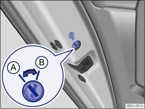 Fig. 32 In the left rear door: Child safety lock Ⓐ deactivated, Ⓑ activated.
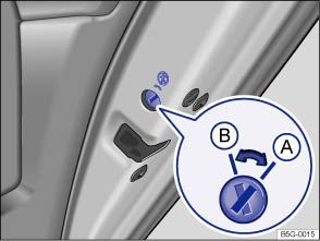 Fig. 33 In the right rear door: Child safety lock Ⓐ deactivated, Ⓑ activated.Read and follow the introductory information and safety information first⇒Introduction to the subject
Slot position ⇒ Fig. 32 or ⇒ Fig. 33 :
 Child safety lock disengaged.
 Child safety lock engaged.
The child safety lock keeps the rear doors from being opened from the inside, so that children cannot open them accidentally. When the child safety lock is engaged, the rear doors can only be opened from the outside.
WarningWhen the child safety lock is engaged, that rear door cannot be opened from the inside.
Introduction to the subjectIn this chapter you will find information on the following subjects:⇒ Display ⇒ Opening the trunk lid ⇒ Closing the trunk lid WarningAccidents and severe personal injuries can result if you unlock, open, or close the trunk lid when someone is in the way.
NoteBefore opening or closing the trunk lid, make sure there is enough room to do so, for example, when the vehicle has a trailer or is in a garage.NoteNever use the gas strut to hold or clamp a load in place. This can damage the trunk lid and make it impossible to close.
Read and follow the introductory information and safety information first⇒Introduction to the subject
| Lights up | Proper response |
|---|---|
| Icon appears in the display ⇒ Displays |
Trunk lid open or improperly closed. Open the trunk lid and then close it again. |
When the ignition is switched on, several warning and indicator lights come on briefly for a function check. They go out after a few seconds.
If the trunk lid is not closed properly, the vehicle icon appears in the instrument cluster display showing an open trunk lid ⇒ Fig. 12 .
Depending on your vehicle's equipment and options, the icon may still be displayed even after the ignition is switched off as long as the key has not been taken out of the ignition. The instrument cluster display goes out about 15 seconds after the vehicle has been locked.
WarningIf the trunk lid is not closed properly, it may open suddenly when the vehicle is moving and cause severe injuries.
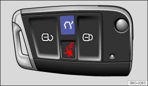 Fig. 34 On the remote control vehicle key: Button to unlock the trunk lid.
 Fig. 35 Opening trunk lid from the outside.Read and follow the introductory information and safety information first⇒Introduction to the subject
Always remove any item(s) being transported on the trunk lid before opening it ⇒ .
Press and hold the button on the remote control vehicle key ⇒ Fig. 34 to unlock the trunk lid. Then open the trunk lid using the Volkswagen emblem.
WarningImproper or unsupervised unlocking or opening of the trunk lid can cause severe injuries. Never open the trunk lid when someone is in the way.
NoteBefore opening or closing the trunk lid, make sure there is enough room to do so, for example, when the vehicle has a trailer or is in a garage.At temperatures below +32 °F (0 °C), the trunk lid may be difficult to open after you unlock it.
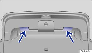 Fig. 36 Opened trunk lid: Recessed grips for closing.Read and follow the introductory information and safety information first⇒Introduction to the subject
If you unlock the vehicle with the vehicle key, but do not open either a door or the trunk lid within several seconds, the vehicle is automatically locked again. This feature helps prevent you from leaving the vehicle unlocked unintentionally.
It is only possible to lock the trunk lid when it is securely closed and latched.
WarningImproper or unsupervised closing of the trunk lid can cause severe injuries. Never close the trunk lid when someone is in the way.
Make sure that the remote control vehicle key is not in the luggage compartment before closing the trunk lid.
Introduction to the subjectIn this chapter you will find information on the following subjects:⇒ Opening or closing power windows ⇒ Power windows – features ⇒ Power window pinch protection WarningImproper use of power windows can result in serious personal injury.
NoteIf you leave the windows open, rain or other precipitation may enter the vehicle from outside and can damage the vehicle interior.
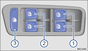 Fig. 37 In the driver door: Switches for the front and rear power windows (4-door version shown).Read and follow the introductory information and safety information first⇒Introduction to the subject
Key to ⇒ Fig. 37 :
For the windows in the front doors.For the windows in the rear doors.Safety switch.| Function | Action |
|---|---|
| Opening: |
Press the |
| Closing: |
Pull the |
| Stopping automatic movement: | Press/pull the respective switch again. |
|
|
The safety switch ⇒ Fig. 37③ deactivates the power windows in the rear doors. The yellow indicator light in the switch comes on (4-door models only). |
The power windows function only when the ignition is switched on.
You can still use the power windows for several minutes after the ignition is switched off as long as the driver or front passenger door has not been opened. When the vehicle key has been removed from the ignition and the driver door has been opened, the power windows cannot be opened or closed.
A separate switch for controlling the passenger side window is located in the front passenger door.
Read and follow the introductory information and safety information first⇒Introduction to the subject
The one-touch feature automatically opens/closes a power window all the way. The window switch does not have to be held down/up.
For one-touch opening: Press the switch for the window down briefly as far as it goes.
For one-touch closing: Pull the switch for the window up briefly as far as it goes.
Stopping automatic movement: Pull/press the switch again.
If the vehicle battery is disconnected or dead and the windows are not completely closed, the one-touch feature will not work and must be reactivated:
The one-touch feature can be reactivated for one or more windows at the same time.
Your vehicle may be equipped with the convenience opening and closing feature.
The convenience opening and closing feature lets you open and close the windows and the power sunroof when the ignition is switched off:
On appropriately equipped vehicles, you can configure settings for the convenience opening feature in the Infotainment system by pressing the button followed by the
and Opening and closing function keys ⇒ Menu and system settings .
WarningImproper use of power windows can result in serious personal injury.
If the power windows malfunction, the one-touch feature, as well as pinch protection may not work properly. See an authorized Volkswagen dealer or authorized Volkswagen Service Facility right away.Convenience closing only works when the one-touch feature is active.
Read and follow the introductory information and safety information first⇒Introduction to the subject
Pinch protection can help reduce the risk of pinching injuries when closing a power window ⇒ . If one-touch window closing meets resistance or there is something in the way, the window will stop and go down again.
.WarningWithout pinch protection, power windows will close with enough force to cause serious personal injury.
Pinch protection is also active during convenience closing of the windows and the power sunroof ⇒ Power windows – features .
Introduction to the subjectIn this chapter you will find information on the following subjects:⇒ Opening or closing the power sunroof ⇒ Power sunroof – features ⇒ Pinch protection for the power sunroof
Depending on equipment, your vehicle may be equipped with a Panoramic sliding and tilting sunroof.
WarningImproper use of the power sunroof can result in serious personal injury.
Note
Remove leaves and other objects from the sunroof guiderails regularly either by hand or using a vacuum cleaner.If the power sunroof malfunctions, pinch protection may not function properly. See an authorized Volkswagen dealer or an authorized Volkswagen Service Facility.
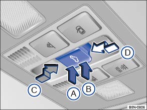 Fig. 38 In the headliner: Power sunroof switch.Read and follow the introductory information and safety information first⇒Introduction to the subject
You must switch on the ignition to operate the power sunroof. After switching off the ignition, you can still open or close the power sunroof for several minutes as long as the driver or front passenger door has not been opened.
The switch ⇒ Fig. 38 has 2 detents for each switch position (Ⓐ, Ⓑ, Ⓒ, and Ⓓ), which are described in the following table.
Press the switch to the first detent to completely or partially tilt, open, or close the sunroof. Press the switch briefly to the second detent to activate the one-touch feature (automatic operation). Press the switch again to stop the one-touch feature.
| Function | Action ⇒ Fig. 38 |
|---|---|
| Tilt the power sunroof |
Press the rear area of the switch Ⓑ upward to the first detent. Briefly press the switch to the second detent to activate the one-touch feature. |
| Close the tilted sunroof |
Press the front area of the switch Ⓐ upward to the first detent. Briefly press the switch to the second detent to activate the one-touch feature. |
| Stop the one-touch feature during tilting/closing | Press the button again at position Ⓐ or Ⓑ. |
| Open the power sunroof |
Press the switch rearward Ⓒ to the first detent. Briefly press the switch to the second detent to open the roof to the comfort position with the one-touch feature. |
| Close the power sunroof |
Press the switch forward Ⓓ to the first detent. Briefly press the switch to the second detent to activate the one-touch feature. |
| Stop the one-touch feature during opening/closing | Press the switch again at Ⓒ or Ⓓ. |
The sliding sunshade must be opened and closed manually. Use the handle at the front of the shade to slide it to the required position. It does not open or close automatically with the power sunroof.
If your power sunroof will not close properly, do not try to close it yourself, doing so can cause serious and expensive damage that will not be covered by any Volkswagen Limited Warranty. Special knowledge and tools are required to close the power sunroof if it will not close on its own. To help prevent damage to the sunroof, have an authorized Volkswagen dealer or an authorized Volkswagen Service Facility help you close and repair the power sunroof.
The comfort position provides sufficient ventilation without loud wind noise.
Read and follow the introductory information and safety information first⇒Introduction to the subject
Your vehicle may be equipped with the convenience opening and closing feature.
The convenience opening and closing feature lets you open and close the windows and the power sunroof when the ignition is switched off:
On appropriately equipped vehicles, you can configure settings for the convenience opening feature in the Infotainment system by pressing the button followed by the
and Opening and closing function keys ⇒ Menu and system settings .
Read and follow the introductory information and safety information first⇒Introduction to the subject
Pinch protection can help reduce the risk of pinching injuries when closing the power sunroof ⇒ . If the power sunroof closing meets resistance or there is something in the way, the power sunroof opens again immediately.
WarningWithout pinch protection, the power sunroof will close with enough force to cause serious personal injury.
Pinch protection is also active during convenience closing of the windows and the power sunroof ⇒ Power sunroof – features .If the power sunroof malfunctions, pinch protection may not function properly. See an authorized Volkswagen dealer or an authorized Volkswagen Service Facility for assistance.
Introduction to the subjectIn this chapter you will find information on the following subjects:⇒ Examples of improper seating positions ⇒ Proper seating position ⇒ Manual controls on the driver and front passenger seats ⇒ Electrical controls on the driver and front passenger seats ⇒ Adjusting the front and rear head restraints ⇒ Removing and reinstalling the front head restraints ⇒ Removing and reinstalling the rear head restraints ⇒ Adjusting the steering wheel position ⇒ Center armrest (Golf, Golf GTI) ⇒ Center armrest (Golf R)
The vehicle has a total of 5 seating positions: 2 in front and 3 in the rear. Each seating position has a safety belt.
WarningImproper seating positions increase the risk of severe or fatal injuries in a crash or other accidents, especially when the airbag deploys.
WarningAlways adjust seat, safety belts, and head restraints properly before driving and make sure that all passengers are properly restrained.
WarningImproper adjustment of the seats can cause accidents and severe injuries.
WarningSome kinds of cigarette lighters can be lit unintentionally, or crushed causing a fire that can result in serious burns and vehicle damage.
Read and follow the introductory information and safety information first⇒Introduction to the subject
Not wearing or improperly fastening safety belts increases the risk of severe or fatal injuries. Safety belts can work only when they are properly positioned on the body. An improper seating position significantly impairs the protection provided by safety belts. This can cause severe or even fatal injuries. Improper seating positions also increase the risk of serious injury or death when an airbag deploys and strikes an occupant who is not in the proper seating position. The driver is responsible for all passengers and especially children riding in the vehicle.
The following are only some examples of seating positions that will increase the risk of serious injury or death.
WarningContact with parts of the vehicle interior can cause serious personal injury in a crash.
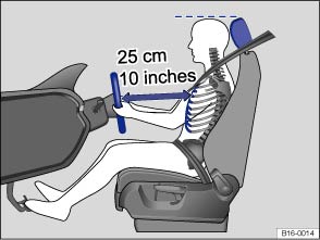 Fig. 39 The driver should never sit closer than 10 inches (25 cm) from the steering wheel.
 Fig. 40 Proper safety belt positioning and head restraint adjustment.Read and follow the introductory information and safety information first⇒Introduction to the subject
The following describes the proper seating positions for the driver and passengers.
If you have a physical impairment or condition that prevents you from sitting properly on the driver seat with the safety belt properly fastened and reaching the pedals, special modifications to your vehicle may be necessary. Only the proper seating position ensures optimum protection by the safety belt and airbag.
Contact your authorized Volkswagen dealer or authorized Volkswagen Service Facility or call the Volkswagen Customer CARE Center at 1-800-822-8987 for information about possible modifications to your vehicle.
For your own safety and to reduce injuries in the event of sudden braking maneuvers or accidents, Volkswagen recommends the following seating positions:
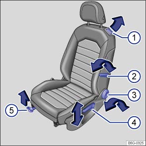 Fig. 41 Driver seat: Manual seat adjustment controls.Read and follow the introductory information and safety information first⇒Introduction to the subject
The manual controls on the front passenger seat either mirror those on the driver seat or there may be different combinations of manual and electrical controls, depending on vehicle equipment.
The illustration and information in this section describes all possible seat controls. The number of controls may vary depending on the version of the seat.
There may be manual and electrical controls on the same seat.
| ⇒ Fig. 41 | Function | Action |
|---|---|---|
| ① | Fold the seat backrest forward or back into place (2-door vehicles only). | Folding forward: Pull lever and fold seat backrest forward. Push the seat forward at the same time. |
| Folding back into place: Slide the seat back as far as it will go until it clicks into place. The backrest releases automatically and can be folded backwards. Engage the seat backrest in an upright position. | ||
| ② | Adjust the lumbar support. | Push the lever forward or pull it backward. |
| ③ | Adjust the backrest angle. |
Lean forward and turn the adjuster wheel forward or backward. If the vehicle has an electrical control for adjusting the backrest angle, see ⇒ Fig. 42② . |
| ④ | Adjust the seat height. | Move the lever several times up or down. |
| ⑤ | Move the front seat forward or back. | Pull the lever up and move the front seat. The front seat must lock in place after the lever is released! |
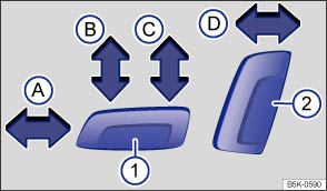 Fig. 42 Driver seat: Electrical controls to move the seat backward or forward, and adjust seat cushion height and backrest angle (if equipped).
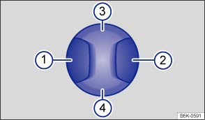 Fig. 43 Lumbar support control (if equipped).Read and follow the introductory information and safety information first⇒Introduction to the subject
If your vehicle is equipped with electrical controls for the front seats, the controls on the front passenger seat either mirror those on the driver seat or there may be different combinations of electrical and manual controls.
There may be manual and electrical controls on the same seat.
| Press the switch in the direction of the arrow ⇒ Fig. 42 : | ||
|---|---|---|
| ① | Ⓐ | Slide the seat forward or back. |
| Ⓑ | Adjust the seat cushion angle. | |
| Ⓒ | Raise or lower the seat cushion. | |
| ② | Ⓓ | Adjust the backrest angle. |
| Press the switch in the corresponding area ⇒ Fig. 43 : | |
|---|---|
| ① or ② | Adjust the curve of the lumbar support. |
| ③ or ④ | Adjust the height of the lumbar support. |
WarningImproper use of electrical seat controls can cause serious personal injuries.
NoteTo help prevent damage to electrical parts in the seat, do not kneel on the front seats or apply concentrated pressure to a small area of the seat or backrest.If the vehicle battery is too weak, the electrical seat adjustment controls may not work.When entering and exiting the vehicle, be careful not to come into contact with any switches that could change the seat adjustment.
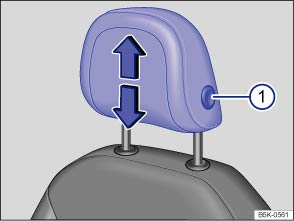 Fig. 44 Adjusting the front head restraints.
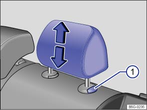 Fig. 45 Adjusting the rear head restraints.Read and follow the introductory information and safety information first⇒Introduction to the subject
All seats are equipped with head restraints. The rear center head restraint is designed only for the center seat on the rear bench. Therefore, only install the center head restraint in the center position.
There are notches in the head restraint guide rods so that the head restraint can lock into place. Only properly installed head restraints can lock into place at the adjustment range notches. In order to prevent inadvertent removal of the head restraints after installation, there are stops at the top and bottom of the adjustment range.
.Adjust head restraints so that the upper edge of the head restraint is at least at eye level or higher. Position the back of the head as close as possible to the head restraint.
Push the head restraint down as far as it will go, even if this means the person's head is still below the top edge of the head restraint. A small gap may remain between the head restraint and the backrest when the head restraint is all the way down.
Pull the head restraint up as far as it will go.
WarningDriving without head restraints or with improperly adjusted head restraints increases the risk of serious injuries in a collision.
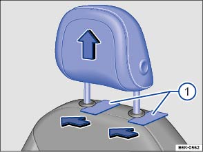 Fig. 46 Removing the front head restraints.Read and follow the introductory information and safety information first⇒Introduction to the subject
All seats are equipped with head restraints. For instructions on removing and reinstalling the rear head restraints, see ⇒ Removing and reinstalling the rear head restraints .
. Recline the backrest with the head restraint so that there is enough overhead clearance to remove it.WarningDriving without head restraints or with improperly adjusted head restraints increases the risk of serious injuries in a collision.
NoteWhen removing or reinstalling the head restraint, take care that the head restraint does not strike the headliner or other parts of the vehicle. The headliner or other parts of the vehicle could otherwise be damaged.
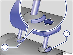 Fig. 47 Removing the rear head restraint (version A).
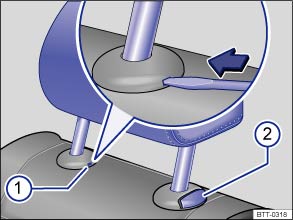 Fig. 48 Removing the rear head restraint (version B).Read and follow the introductory information and safety information first⇒Introduction to the subject
All seats are equipped with head restraints. The rear center head restraint is designed only for the center seat on the rear bench. Therefore, only install the center head restraint in the center position. For instructions on removing and reinstalling the front head restraints, see ⇒ Removing and reinstalling the front head restraints
. .WarningDriving without head restraints or with improperly adjusted head restraints increases the risk of serious injuries in a collision.
NoteWhen removing or reinstalling the head restraint, take care that the head restraint does not strike the headliner or other parts of the vehicle. The headliner or other parts of the vehicle could otherwise be damaged.
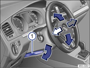 Fig. 49 Manual adjustment for the steering wheel position.
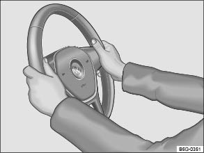 Fig. 50 Steering wheel: 9 o'clock and 3 o'clock positions.Read and follow the introductory information and safety information first⇒Introduction to the subject
Adjust the steering wheel only when the vehicle is not moving.
.WarningImproper use of the steering column adjustment feature can result in serious personal injury and even death.
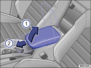 Fig. 51 Front center armrest.
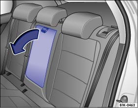 Fig. 52 Folding down the rear center armrest (arrow).Read and follow the introductory information and safety information first⇒Introduction to the subject
There may be a storage compartment under the front center armrest ⇒ Storage areas .
To raise the center armrest, push the release button, pull the armrest up, and latch upward in the direction of the arrow ⇒ Fig. 51① .
To lower the center armrest, first lift it all the way up. Then you can push the center armrest down until it latches in place.
To move the center armrest forward and backward, pull it forward in the direction of the arrow ②, or slide it backward until it clicks into place.
There may be a fold-down armrest in the backrest of the center rear seat ⇒ Fig. 52 .
To fold down, pull the loop in the direction of the arrow ⇒ Fig. 52 .
To fold up, push the center armrest up as far as it will go.
WarningThe center armrest can restrict the driver's arm movement and cause crashes and serious personal injury.
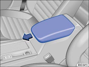 Fig. 53 Front center armrest.Fig. 54 Folding down the rear center armrest (arrow).Read and follow the introductory information and safety information first⇒Introduction to the subject
There is a front center armrest between the driver and front passenger seats ⇒ Fig. 53 .
To move the center armrest forward and backward, pull it forward in the direction of the arrow or slide it backward until it clicks into place.
There may be a fold-down armrest in the backrest of the center rear seat ⇒ Fig. 54 .
To fold down, pull the loop in the direction of the arrow ⇒ Fig. 54 .
To fold up, push the center armrest up as far as it will go.
WarningThe center armrest can restrict the driver's arm movement and cause crashes and serious personal injury.
Introduction to the subjectIn this chapter you will find information on the following subjects:⇒ Seat heating WarningImproper use of seat adjustment controls can cause severe personal injuries.
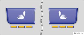 Fig. 55 In the center console: Seat heating buttons for the front seats.Read and follow the introductory information and safety information first⇒Introduction to the subject
Your vehicle may be equipped with a seat heating feature.
When the ignition is switched on, the front seats can be electrically heated by heating elements that warm the seat backrest and cushion.
Depending on vehicle equipment, the seat heating on the driver and passenger side may automatically resume at the setting that was set when the ignition was last switched off.
Do not use the seat heating if any of the following conditions apply:
| Function | Action for seat heating ⇒ Fig. 55 |
|---|---|
| Switch on: |
Press the |
| Adjust the heating level: |
Press the |
| Switch off: |
Press the |
People suffering from a low level of perceived pain or a lowered awareness of pain as from medication, paralysis, or chronic illness (e.g. diabetes) should NEVER use the seat heating feature ⇒ !
The use of seat heating by persons with these conditions could result in burns to the back, buttocks, and legs that may take a long time to heal and may never heal completely. If you have any of these conditions, you should take regular breaks and get out of the vehicle, particularly on long trips. Consult your doctor for advice regarding your specific condition.
WarningCertain medical conditions, such as paralysis and diabetes, and certain medications can increase the risk of serious burns when the seat heating feature is switched on.
WarningA wet seat can cause the seat heating to malfunction and increase the risk of serious burns.
Note
Switch off seat heating when it is not needed to help reduce unnecessary fuel consumption.
Introduction to the subjectIn this chapter you will find information on the following subjects:⇒ Warning light ⇒ Frontal collisions and laws of physics ⇒ What happens to passengers not wearing a safety belt ⇒ Safety belts protect ⇒ Using safety belts ⇒ Fastening and unfastening safety belts ⇒ Safety belt position ⇒ Safety belt height adjusters ⇒ Safety belt extender ⇒ Safety belt retractor, pretensioner, load limiter ⇒ Service and disposal of belt pretensioners
Properly worn safety belts are the single most effective means of reducing the risk of serious injury and death in a collision or other accident.
Damage to safety belts reduces their overall effectiveness and increases the risk of serious personal injury and death whenever the vehicle is being used.
Check the condition of all safety belts regularly.
If a safety belt shows damage to webbing, bindings, retractors or buckles, have the safety belt replaced by an authorized Volkswagen dealer or an authorized Volkswagen Service Facility ⇒ .
WarningNot wearing a safety belt or wearing an improperly positioned safety belt increases the risk of severe personal injury or death. Safety belts offer optimum protection only when they are used properly.
WarningDamage to safety belts reduces their overall effectiveness and increases the risk of serious personal injury and death whenever the vehicle is being used.
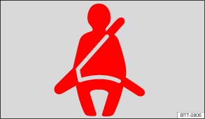 Fig. 56 Warning light in the instrument cluster.Read and follow the introductory information and safety information first⇒Introduction to the subject
| Lights up or flashes | Possible cause | Proper response |
|---|---|---|
|
|
Driver and front passenger have not fastened their safety belts, if front passenger seat is occupied. | Fasten safety belts. |
When the ignition is switched on, several warning and indicator lights come on briefly for a function check. They go out after a few seconds.
A warning chime also sounds.
The safety belt warning light comes on for 6 seconds when the ignition is switched on. A warning chime also sounds for up to 6 seconds if the driver's safety belt is not buckled. The chime stops sooner if the driver buckles his or her safety belt. The warning light and the chime go out when both driver and front passenger have buckled their safety belts.
If the driver and front seat passenger do not both fasten their safety belts within about 24 seconds after the chime stops and the vehicle is moving at a speed of more than about 15 mph (25 km/h), the chime will again sound for about 6 seconds, then go off for about 24 seconds, then sound again for about another 6 seconds. The same thing happens if one of the safety belts is fastened and then unfastened while the vehicle is moving. The safety belt warning light also flashes. The warning chime continues to sound at 24 second intervals for up to 2 minutes. No chime sounds at speeds of less than about 5 mph (8 km/h).
If the ignition is switched on, the safety belt warning light stays on until the driver and front passenger have both buckled their safety belts.
WarningNot wearing a safety belt or wearing an improperly positioned safety belt increases the risk of severe personal injury or death. Safety belts offer optimum protection only when used correctly.
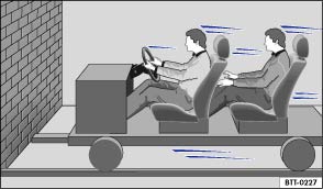 Fig. 57 A vehicle with passengers not wearing safety belts approaches a wall.
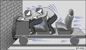 Fig. 58 A vehicle with passengers not wearing safety belts hits a wall.Read and follow the introductory information and safety information first⇒Introduction to the subject
The physical principles of a frontal collision are simple. Both the moving vehicle and the passenger possess energy ⇒ Fig. 57 , which varies with vehicle speed and body weight. Engineers call this energy kinetic energy.
The higher the speed of the vehicle and the greater the vehicle's weight, the more energy has to be absorbed in a crash.
Vehicle speed is the most significant factor. If your speed doubles (for example, from 15 mph to 30 mph – 25 km/h to 50 km/h), the energy increases 4 times!
Because the occupants of the vehicle in the above example are not using safety belts, they are not attached to the vehicle. In a frontal collision, they will keep moving at the same speed the vehicle was moving just before the crash, until something stops them - here, the inside of the passenger compartment. Because the occupants of the vehicle in the example are not wearing safety belts, their entire kinetic energy will be absorbed by impact with the wall ⇒ Fig. 58 .
The same principles apply to people in a vehicle that is in a frontal collision on the highway. Even at city speeds of 20–30 mph (30–50 km/h), the forces acting on the body can reach one ton (2,000 lbs or 1,000 kg) or more. At greater speeds, these forces are even higher.
Of course, the laws of physics don't apply just to frontal collisions; they determine what happens in all kinds of accidents and collisions.
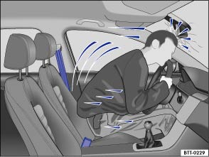 Fig. 59 The unbelted driver is thrown forward.
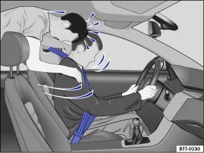 Fig. 60 Unbelted passengers in the rear seats are thrown forward on top of the belted driver.Read and follow the introductory information and safety information first⇒Introduction to the subject
Many people believe that it is possible to resist the forces of an impact by holding tight or bracing themselves. That is simply not true!
Even at low collision speeds, the forces acting on the body are too much for the body to be held in the seat with the arms and hands. In a frontal collision, unrestrained occupants will slam violently into the steering wheel, instrument panel, windshield or anything else in the way ⇒ Fig. 59 .
Never rely on airbags alone for protection. Even when they deploy, airbags provide only additional protection. Airbags are not supposed to deploy in all kinds of accidents. Even if your vehicle is equipped with airbags, all vehicle occupants, including the driver, must wear safety belts correctly in order to minimize the risk of severe injury or death in a crash, regardless of whether a seating position has an airbag or not.
An airbag will deploy only once. Safety belts are always there to offer protection in those accidents in which airbags are not supposed to deploy or when they have already deployed. Unbelted occupants can also be thrown out of the vehicle, causing even more severe injuries or death.
It is also important for occupants in the rear seats to wear their safety belts properly since they can be thrown violently forward through the vehicle in the event of an accident. Unbelted passengers in the rear seats endanger not only themselves but also the driver and other passengers in the vehicle ⇒ Fig. 60 .
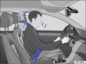 Fig. 61 Belted driver secured by the correctly worn safety belt in the event of a sudden braking maneuver.Read and follow the introductory information and safety information first⇒Introduction to the subject
Used properly, safety belts can make a big difference. Safety belts help to keep passengers in their seats, gradually reduce energy levels applied to the body in a collision, and help prevent the uncontrolled movement that can cause serious injuries. In addition, safety belts reduce the danger of being thrown out of the vehicle ⇒ Fig. 61 .
Safety belts attach passengers to the car and give them the benefit of being slowed down more gently or softly through the give in the safety belts, crumple zones, and other safety features (such as airbags) engineered into today's vehicles. The front crumple zones and other passive safety features (such as the airbag system) are also designed to absorb kinetic energy. By absorbing the kinetic energy over a longer period of time, the forces on the body become more tolerable and less likely to cause injury.
Although these examples are based on a frontal collision, safety belts can also substantially reduce the risk of injury in other kinds of crashes. So, whether you're on a long trip or just going to the corner store, always buckle up and make sure that others do, too.
Accident statistics show that vehicle occupants properly wearing safety belts have a lower risk of being injured and a much better chance of surviving a collision. Properly using safety belts also greatly increases the ability of the supplemental airbags to do their job in a collision. For this reason, wearing a safety belt is required by law in most countries including the United States and Canada.
Although your Volkswagen is equipped with airbags, you still have to wear the safety belts provided. Front airbags, for example, are activated only in some frontal collisions. The front airbags are not activated in all frontal collisions, in side and rear collisions, in rollovers, or in cases when the conditions for deployment stored in the electronic control unit are not met. The same goes for the other airbag systems on your Volkswagen.
So always wear your safety belt and make sure that everybody in your vehicle is properly restrained!
Read and follow the introductory information and safety information first⇒Introduction to the subject
Damage to safety belts reduces their overall effectiveness and increases the risk of serious personal injury and death whenever the vehicle is being used.
Check the condition of all safety belts regularly.
Keep safety belts clean.
Keep objects and liquids away from safety belt webbing, the safety belt buckle tongue, and the safety belt buckle latch and opening.
Do not pinch or damage the safety belt or buckle tongue (for instance, when closing a door).
Never modify, disassemble or try to repair safety belts and safety belt anchorages.
Always fasten your safety belt properly before driving and keep it fastened whenever the vehicle is moving.
If it is difficult to pull the safety belt out of the belt guide, the belt may be twisted inside the side trim because the belt retracted too quickly when it was taken off.
If you cannot untwist the safety belt, wear it anyway. Make sure that the safety belt is twisted in a spot where it does not come in direct contact with your body. Have the safety belt untwisted immediately by an authorized Volkswagen dealer or authorized Volkswagen Service Facility.
The retractors for the rear seat safety belts and the front passenger safety belt have a switchable locking feature for child restraints in addition to the emergency locking feature. Whenever a child restraint is installed with a safety belt, the safety belt must be locked so that the safety belt webbing cannot unreel. The switchable locking feature lets you lock the belt so that a child restraint can be properly installed and, for example, so that it can't tip to the side when the vehicle goes around a corner ⇒ Child safety and child restraints .
To see whether a safety belt is lockable, pull the safety belt all the way out of the safety belt retractor. You should then hear a clicking sound as the belt winds back into the retractor reel. Test the switchable locking feature by pulling on the belt. When the switchable locking feature is active, you should no longer be able to pull the belt out of the retractor.
The locking feature must be deactivated when a vehicle occupant uses the safety belt.
WarningImproper use and care of safety belts increases the risk of severe personal injury or death.
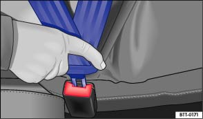 Fig. 62 Inserting the buckle tongue into the belt buckle.
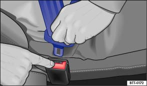 Fig. 63 Releasing the buckle tongue from the belt buckle.Read and follow the introductory information and safety information first⇒Introduction to the subject
Properly worn safety belts help to hold occupants in their seats and provide optimum protection during braking or in a collision or other accident ⇒ .
The switchable locking feature makes a clicking sound when the safety belt is winding back onto the safety belt retractor wheel after being pulled all the way out. Whenever a child restraint is installed with a safety belt, the safety belt must be locked so that the safety belt webbing cannot unreel ⇒ Child safety and child restraints . If active, deactivate the locking feature before using the safety belt to restrain a person without a child restraint system.
Always buckle your safety belt before driving.
. .Unfasten safety belts only when the vehicle is not moving ⇒ .
WarningImproperly positioned safety belts can cause serious personal injury or death in an accident.
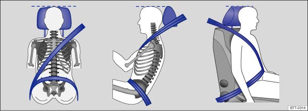 Fig. 64 Proper safety belt positioning and head restraint adjustment.
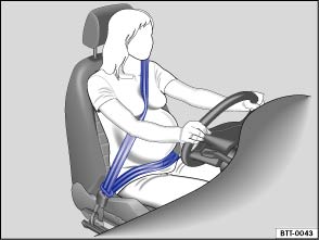 Fig. 65 Proper safety belt positioning for expectant mothers.Read and follow the introductory information and safety information first⇒Introduction to the subject
Wearing safety belts improperly can cause serious injury or death. Safety belts can only work when they are correctly positioned on the body. A properly worn safety belt also helps to position the occupant so that an airbag can provide maximum protection when deployed. Therefore, always fasten your safety belt and make sure that it is properly positioned over your body.
Improper seating positions reduce the effectiveness of safety belts and even increase the risk of injury or death by moving the safety belt to critical areas of the body. Improper seating positions also increase the risk of severe injury or death when an airbag deploys and strikes an occupant who is not seated properly ⇒ Adjusting the seating position .
Expectant mothers must always wear the lap portion of the safety belt as low as possible across the pelvis and below the rounding of the abdomen – throughout the pregnancy. The safety belt must lie flat against the body to avoid pressure against the abdomen ⇒ Fig. 65 .
The safety belt position can be adjusted using the following features:
WarningImproperly positioned safety belts can cause serious personal injury in an accident or a sudden braking maneuver.
If you have a physical impairment or condition that prevents you from sitting properly on the seat with the safety belt properly fastened, special modifications to your vehicle may be necessary. Contact your authorized Volkswagen dealer or authorized Volkswagen Service Facility or call the Volkswagen Customer CARE Center at 1-800-822-8987 for information about possible modifications to your vehicle.
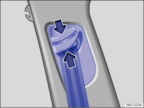 Fig. 66 Next to the front seats: Safety belt height adjuster.Read and follow the introductory information and safety information first⇒Introduction to the subject
Safety belt height adjusters for the front seats can be used to adjust the height of the shoulder portion of the safety belt so that it is positioned correctly:
WarningNever adjust the height of the safety belt while driving.
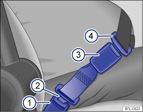 Fig. 67 A safety belt extender properly attached to the factory-installed safety belt.
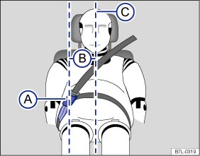 Fig. 68 Positioning of the safety belt extender.Read and follow the introductory information and safety information first⇒Introduction to the subject
If a safety belt is too short to correctly fit you or one of your passengers, even when the safety belt is pulled out all the way, you can use a safety belt extender.
Never use the safety belt extender for any other purpose – including the attachment of a child restraint.
The extender adds about 8 inches (20 cm) to the safety belt. Always remove the safety belt extender when it is not needed and stow it safely. Contact an authorized Volkswagen dealer or authorized Volkswagen Service Facility if you believe you may need an extender.
Key to⇒ Fig. 67 :
Vehicle safety belt buckle.Buckle tongue on the safety belt extender.Safety belt buckle on the safety belt extender.Safety belt buckle tongue on the factory-installed safety belt.Key to⇒ Fig. 68 :
Safety belt buckle on the safety belt extender.Distance between the safety belt buckle on the safety belt extender and the centerline of the person using the safety belt extender. The distance must be more than 6 inches (15 cm)! Centerline of the person using the safety belt extender.
WarningImproper use or positioning of a safety belt extender increases the risk of serious personal injury and death.
Note
NoteIf the safety belt extender is left attached to the safety belt buckle, the safety belt warning system will sense that the safety belt for that seat is being used. The warning light will not come on and the warning chime will not sound even though the seat is occupied and the safety belt is not being used.
Read and follow the introductory information and safety information first⇒Introduction to the subject
The safety belts in the vehicle are part of the vehicle's safety concept ⇒ Safety equipment and consist of the following important features:
Every safety belt is equipped with an automatic safety belt retractor on the shoulder belt. As long as the safety belt is pulled out slowly, the shoulder belt will extend to let you move freely under normal driving conditions. The automatic safety belt retractor locks the belt when the belt is pulled out fast, during hard braking and in a collision. The belt may also lock when you drive up or down a steep hill or through a sharp curve.
The safety belt retractors for the driver and front seat passenger have a pretensioner that helps take the slack out of the safety belt and tighten it when the pretensioner is activated.
The pretensioners are activated by the electronic control unit for the airbag system in front, side, and rear collisions. By tightening the safety belt, the pretensioner helps to reduce the occupant's forward movement. The belt pretensioner works together with the airbag system; its function is monitored by the airbag system indicator light. The belt pretensioner will not deploy in a rollover if the side airbags are not activated.
A fine dust may be released upon activation. This is normal and is not caused by a fire in the vehicle.
The front and rear outboard safety belts also have load limiters to help reduce the forces applied to the body in a crash.
Heed all safety regulations if the vehicle or individual components of the system have to be scrapped. Your authorized Volkswagen dealer and authorized Volkswagen Service Facility are familiar with these regulations ⇒ Service and disposal of belt pretensioners .
Read and follow the introductory information and safety information first⇒Introduction to the subject
The pretensioners are part of the safety belts installed at the front seats in your vehicle. Installing, removing, servicing, or repairing of safety belt pretensioners can damage the safety belt system and prevent it from working correctly in a collision. The pretensioners themselves may then also not work in the event of an accident, or not work properly.
There are some important things you have to know to make sure that the effectiveness of the system will not be impaired and that discarded components do not cause injury or pollute the environment. Undeployed safety belt pretensioners and airbag modules contain explosive materials that can cause serious injuries to the general public and to people who work at dealerships and workshops, scrap yards, and recycling facilities. For this reason, the systems must be properly handled when they or the vehicles they are installed in are scrapped.
Undeployed safety belt pretensioners and airbag modules can also pollute the environment. Never abandon vehicles or vehicle parts. If your vehicle must be scrapped, please make sure that it is done safely, responsibly, and in compliance with all applicable environmental regulations. Take it to a licensed facility that has the knowledge and experience to properly dispose of the vehicle and its safety belt system. Your authorized Volkswagen dealer and authorized Volkswagen Service Facility are familiar with these regulations.
WarningImproper handling, care, servicing, and repair procedures can increase the risk of personal injury and death by preventing a belt pretensioner from activating when needed or by causing it to activate unexpectedly.
WarningUndeployed safety belt pretensioners and airbag modules contain explosive materials that can cause serious personal injuries if they are not properly handled when they or the vehicles they are installed in are scrapped.
Undeployed airbag modules and safety belt pretensioners are classified as Perchlorate Material. Special handling may apply – see http://www.dtsc.ca.gov/hazardouswaste/perchlorate. Obey all applicable legal requirements regarding handling and disposal of the vehicle or parts of its restraint system, including airbag modules and safety belts with pretensioners. Authorized Volkswagen dealers and authorized Volkswagen Service Facilities are familiar with the requirements, and we recommend that you have them perform this service for you.
Introduction to the subjectIn this chapter you will find information on the following subjects:⇒ Advanced Airbag System, infants, child restraints and children on the front seat ⇒ Monitoring the Advanced Airbag System ⇒ PASSENGER AIR BAG light ⇒ Airbags and how they work ⇒ The dangers of using child restraints on the front seat ⇒ Front airbags ⇒ Advanced Airbag System components ⇒ How to tell if the front passenger front airbag is on or off ⇒ Side airbags ⇒ Side Curtain Protection® airbags for 2-door vehicles ⇒ Side Curtain Protection® airbags for 4-door vehicles
Your vehicle is equipped with a front airbag for the driver and front seat passenger. The front airbags can provide additional protection for the chest and head of the driver and the front seat passenger when seats, safety belts, head restraints and, for the driver, the steering wheel, are properly used and have been properly adjusted. Airbags are only supplemental restraints. They are not a substitute for safety belts that must be worn even though the front seating positions are equipped with front airbags.
WarningNever rely on airbags alone for protection.
WarningSitting too close to the steering wheel or instrument panel will decrease the effectiveness of the airbags and will increase the risk of personal injury in a collision.
WarningObjects between you and the airbag will increase the risk of injury in a crash by interfering with the way the airbag unfolds or by being pushed into you as the airbag inflates.
WarningAn airbag works only once. Airbags that have deployed in a crash must be replaced.
WarningFine dust released when airbags deploy can irritate the skin, eyes, and mucous membranes as well as cause breathing problems for people who suffer from asthma or other respiratory conditions.
WarningUsing solvents or other improper cleaning products on surfaces where airbags are located can change the way airbags deploy in a crash.
Read and follow the introductory information and safety information first⇒Introduction to the subject
Be sure to read the important information and the WARNINGS for important details about children and Advanced Airbags ⇒ Child safety and child restraints .
The Advanced Airbag System in your vehicle has been certified to comply with the requirements of the United States Federal Motor Vehicle Safety Standard (FMVSS) 208, as well as Canada Motor Vehicle Safety Standard (CMVSS) 208 as applicable at the time your vehicle was manufactured. According to requirements, the front Advanced Airbag System on the passenger side has been certified for suppression for infants of about 12 months old and younger and for low risk deployment for children aged 3 to 6 years old (as defined in the standard).
Even though your vehicle is equipped with an Advanced Airbag System, make certain that all children, especially 12 years and younger, always ride on the back seat properly restrained for their age and size. The airbag on the front passenger side makes the front seat a potentially dangerous place for a child to ride. The front seat is not the safest place for a child in a forward-facing child restraint. It is a very dangerous place for an infant or a child in a rearward-facing seat.
Danger!The front seat of any vehicle can be a dangerous place for a child - even with an Advanced Airbag System.
Read and follow the introductory information and safety information first⇒Introduction to the subject
The Advanced Airbag System (including the electronic control unit, sensors and system wiring) is monitored continuously to make sure that it is functioning properly whenever the ignition is on. Every time you turn on the ignition, the airbag system indicator light will come on for a few seconds (function check).
If an airbag system malfunction is detected, the airbag indicator light comes on and stays on to alert the driver to the problem. It also reminds you to have the airbag system checked immediately by an authorized Volkswagen dealer or an authorized Volkswagen Service Facility. If a malfunction occurs that turns the front airbag on the passenger side off, the PASSENGER AIR BAG
light ⇒ PASSENGER AIR BAG
light will come on and stay on whenever the ignition is on.
WarningAn airbag system and safety belt pretensioner that are not working properly cannot provide supplemental protection in a frontal crash.
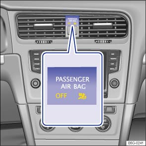 Fig. 69 In the instrument panel: PASSENGER AIR BAG light.Read and follow the introductory information and safety information first⇒Introduction to the subject
| On | Location | Possible cause | Solution |
|---|---|---|---|
|
|
Instrument cluster | Airbag and safety belt pretensioner system malfunction. | See your authorized Volkswagen dealer or authorized Volkswagen Service Facility immediately to have the system checked. |
|
|
Instrument panel ⇒ Fig. 69 | Airbag system malfunction. | See your authorized Volkswagen dealer or authorized Volkswagen Service Facility immediately to have the system checked. |
| Front passenger airbag turned off by Advanced Airbag System. | Check if the airbag must stay turned off. |
The PASSENGER AIR BAG
light ⇒ Fig. 69 will come on and stay on to tell you when the front Advanced Airbag System on the passenger side has been turned off by the electronic control unit.
If the bulb for the PASSENGER AIR BAG
light burns out, the airbag indicator light
⇒ Monitoring the Advanced Airbag System will come on and signal a malfunction in the Advanced Airbag System. Although the burned-out bulb will not change the way the front airbag on the passenger side works, it will no longer be possible to use the PASSENGER AIR BAG
light to make sure that the airbag on/off status is correct for the occupant on the front passenger seat. Have the airbag system inspected immediately by your authorized Volkswagen dealer or authorized Volkswagen Service Facility.
The PASSENGER AIR BAG
light will blink for about 5 seconds when:
After the PASSENGER AIR BAG
light stops blinking, always make sure that the airbag status (on or off) as shown by the PASSENGER AIR BAG
light is proper for the size, age, and weight (electrical capacitance) of the occupant on the front passenger seat. Always make sure that the safety belt for the front passenger seat is properly fastened.
The PASSENGER AIR BAG
light will show the status of the front seat passenger's front Advanced Airbag System a few seconds after the ignition has been switched on and the airbag monitoring light goes off. The PASSENGER AIR BAG
light:
If the front passenger seat is not occupied, the front passenger airbag will not deploy, and the PASSENGER AIR BAG
light will stay on.
Never install a rearward-facing child restraint on the front passenger seat. The safest place for a child in any kind of child restraint is on the rear seat ⇒ Advanced Airbag System, infants, child restraints and children on the front seat , and ⇒ Child safety and child restraints .
If the PASSENGER AIR BAG
light comes on when one of the conditions listed above is met, be sure to check the light regularly to make certain that the PASSENGER AIR BAG
light stays on continuously whenever the ignition is on. If the PASSENGER AIR BAG
light does not come on and stay on all the time, stop as soon as it is safe to do so AND
If the PASSENGER AIR BAG
light still does not come on and does not stay on continuously (when the ignition is switched on), take the child restraint off the front passenger seat and install it properly at one of the rear seat positions. Have the airbag system inspected immediately by your authorized Volkswagen dealer or authorized Volkswagen Service Facility.
The PASSENGER AIR BAG
light should NOT come on when the ignition is on and an adult is sitting in a proper seating position on the front passenger seat. If the PASSENGER AIR BAG
light comes on and stays on under these circumstances, make sure that:
WarningIf the status of the Advanced Airbag System has changed while the vehicle is moving, the PASSENGER AIR BAG
light blinks for about 5 seconds to catch the driver's attention. If this happens, always stop as soon as it is safe to do so and check the steps described above.
WarningIf the PASSENGER AIR BAG
light does not go off when an adult who is not very small is sitting on the front passenger seat after taking the steps described above, make sure the adult is properly seated and restrained at one of the rear seating positions.
If the capacitive passenger detection system determines that the front passenger seat is empty, the front airbag on the passenger side will be turned off, and the PASSENGER AIR BAG
light will stay on.
If the optional safety belt extender is left in the buckle for the front safety belt, or the front passenger safety belt itself is buckled and the front passenger seat is not occupied, the PASSENGER AIR BAG
light will come on.
Read and follow the introductory information and safety information first⇒Introduction to the subject
Airbags are only supplemental restraints. They are not a substitute for safety belts that must be worn even though the front seating positions are equipped with front airbags. The front airbags can provide additional protection for the chest and head of the driver and the front seat passenger when seats, safety belts, head restraints and, for the driver, the steering wheel, are properly used and have been properly adjusted.
When the airbag system deploys in a collision, a gas generator fills the airbags that break open the padded covers on the steering wheel and the instrument panel. The front airbags inflate between the steering wheel and the driver and between the instrument panel and the front passenger.
Front airbags in combination with properly worn safety belts slow down and limit the occupant's forward movement. Together they help to prevent the driver and front seat passenger from hitting parts of the vehicle interior, thereby reducing the forces acting on the occupants during a crash. In this way, they help to reduce the risk of injury to the head and upper body during a crash. Airbags do not provide protection for the arms and lower body parts. It is important to remember that the supplemental airbag system is designed to reduce the likelihood of serious injuries. However, it is possible that a deployed airbag may cause other injuries such as swelling, bruising, friction burns, and abrasions.
Airbags inflate in the blink of an eye, so fast that many people don't even realize that the airbags have deployed. The airbags will deflate immediately after deployment so that the front occupants can see through the windshield again without interruption.
Airbags inflate with a great deal of force. Airbags can cause serious injuries when they inflate and hit those who are sitting too close, are out of position, or are not properly restrained. By keeping room between your body and the steering wheel and the front of the passenger compartment, the airbag can inflate fully and completely and provide supplemental protection during certain frontal collisions ⇒ Safety belts .
Make sure that nothing is in the way of the airbags when they deploy. For example, things on your lap or on the seat could be pushed into your body or fly dangerously through the passenger compartment when the airbag inflates and cause serious personal injury.
The areas outlined in red (dotted lines) ⇒ Fig. 70 and ⇒ Fig. 71 indicate the airbag deployment zone. Never place or attach accessories or other objects (such as cup holders, telephone brackets, note pads, large, heavy or bulky objects) on the doors, on the windshield, over or near the area marked in red (dotted lines).
If you have a physical impairment or condition that prevents you from sitting properly on the driver seat with the safety belt properly fastened and reaching the pedals, special modifications to your vehicle may be necessary. The safety belt and airbag can only provide optimum protection if you are seated correctly and can reach the pedals.
Contact your authorized Volkswagen dealer or authorized Volkswagen Service Facility or call the Volkswagen Customer CARE Center at 1-800-822-8987 for information about possible modifications to your vehicle.
Deployment of the front airbags and the activation of the safety belt pretensioners depend on the deceleration measured by the crash sensors and registered by the electronic control unit. Crash severity depends on speed and deceleration as well as the mass and stiffness of the vehicle or object involved in the crash.
The front airbags will not inflate in side or rear collisions, in rollovers or if the ignition is switched off. The front airbags will not inflate in all frontal collisions. The triggering of the airbag system depends on the vehicle deceleration rate caused by the collision and registered by the electronic control unit. If this rate is below the reference value programmed into the control unit, the airbags will not be triggered, even though the vehicle may be badly damaged as a result of the collision. Vehicle damage, repair costs or even the lack of vehicle damage is not necessarily an indication of whether an airbag should inflate or not. It is not possible to define a range of vehicle speeds that will cover every possible kind and angle of impact that will always trigger the airbags, since the circumstances will vary considerably between one collision and another. Important factors include, for example, the nature (hard or soft) of the object that the vehicle hits, the angle of impact, vehicle speed, etc.
When an airbag deploys, fine dust is released. This is normal and is not caused by a fire in the vehicle. This dust is made up mostly of a powder used to lubricate the airbags as they deploy. This dust could irritate skin and eyes and cause breathing problems for people with asthma or other respiratory conditions.
Always remember: Front airbags only supplement the 3 point safety belts in some frontal collisions only when the vehicle deceleration is high enough to deploy the airbags. Airbags only deploy once, and only in certain kinds of collisions. The safety belts are always there to offer protection in situations in which airbags should not deploy or when they have already deployed, for example, when your vehicle strikes or is struck by another vehicle after an initial collision.
This is just one of the reasons why an airbag is a supplementary restraint and is not a substitute for a safety belt. The airbag system works most effectively when used with the safety belts. Therefore, always buckle up properly and wear your safety belts.
The airbags are part of the overall passive vehicle safety system. The airbag system works most efficiently when used with properly worn safety belts and a proper seating position ⇒ .
Your safety and the safety of your passengers shouldn't be left to chance. Advances in technology have made a number of features available to help reduce the risk of injury in a collision. The following are just a few of the safety features for your Volkswagen:
These individual safety features can work together as a system to help protect you and your passengers in a wide range of collisions. These features can't work as a system if they are not always correctly adjusted and properly used!
On the passenger side, regardless of safety belt use, the front passenger front airbag will be turned off if the electrical capacitance measured by the capacitive passenger detection system on the front passenger seat is less than the amount programmed in the electronic control unit. The front airbag on the passenger side will also be turned off if the capacitance measured by the system for the front passenger seat equals that of an infant of about 1 year of age in one of the child restraints that was used to certify the Advanced Airbag System under Federal Motor Vehicle Safety Standard 208. The PASSENGER AIR BAG
light comes on and stays on to tell you when the front Advanced Airbag System on the passenger side has been turned off ⇒ PASSENGER AIR BAG
light .
WarningNever rely on airbags alone for protection.
WarningSitting too close to the steering wheel or instrument panel will decrease the effectiveness of the airbags and will increase the risk of personal injury in a collision.
WarningObjects between you and the airbag will increase the risk of injury in a crash by interfering with the way the airbag unfolds and/or by being pushed into you as the airbag inflates.
WarningThe fine dust created when airbags deploy can cause breathing problems for people with asthma or other breathing conditions.
WarningTo reduce the risk of serious injury, make sure that the PASSENGER AIR BAG
light is on and stays on whenever a child restraint is installed on the front passenger seat and the ignition is switched on.
WarningAirbags that have deployed in a crash must be replaced.
Read and follow the introductory information and safety information first⇒Introduction to the subject
The airbag on the front passenger side makes the front seat a potentially dangerous place for a child to ride, even if the vehicle is equipped with an Advanced Airbag System. The front seat is a very dangerous place for an infant or small child in a rearward facing child restraint. The front seat is also not the safest place for a child in a forward-facing child restraint. All children, especially 12 years and younger, must always ride on the back seat and be properly restrained for their age and size.
During a frontal collision, a child restraint or infant carrier on the front seat could be hit and knocked out of position by the inflating front passenger airbag. The airbag could significantly reduce the effectiveness of the child restraint and even seriously injure a child while deploying.
Because of this danger, and because children are generally better protected on the rear seat when properly restrained for their age and size, we strongly urge you to always make sure that children ride on the rear seat ⇒ Child safety and child restraints , and ⇒ Advanced Airbag System, infants, child restraints and children on the front seat .
Danger!A front seat passenger, especially an infant or small child, will be seriously injured and can even be killed if too close to the airbag when it deploys – even an Advanced Airbag.
Danger!Children on the front seat of any vehicle, even one with Advanced Airbags, can be seriously injured or even killed when an airbag inflates.
WarningForward-facing child restraints installed on the front passenger seat may interfere with the deployment of the airbag and cause serious personal injury to the child.
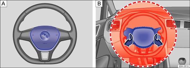 Fig. 70 Location and deployment zone of the driver front airbag.
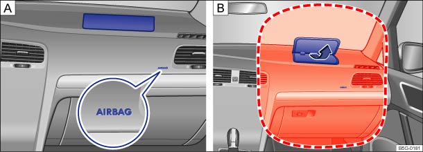 Fig. 71 Location and deployment zone of the front passenger front airbag.Read and follow the introductory information and safety information first⇒Introduction to the subject
The vehicle is equipped with an Advanced Airbag System in compliance with the United States Federal Motor Vehicle Safety Standard (FMVSS) 208 or the Canada Motor Vehicle Safety Standard (CMVSS) 208 applicable at the time your vehicle was manufactured. The airbag for the driver is in the steering wheel hub ⇒ Fig. 70 and the airbag for the front passenger is in the instrument panel ⇒ Fig. 71
. The general location of the airbags is marked AIRBAG.
The safety belts for the front seating positions have safety belt pretensioners which help take up slack in the belts. The airbag control unit also activates the belt pretensioners ⇒ Airbags and how they work .
The safety belts for the front and rear outboard seating positions also have belt load limiters to reduce the forces acting on a body during an accident.
The areas marked in red (dotted lines) ⇒ Fig. 70 and ⇒ Fig. 71
indicate the airbag deployment zone. Never place or attach accessories or other objects (such as cup holders, telephone brackets, note pads, navigation systems, large, heavy or bulky objects) on the doors, on the windshield, over or near the area marked in red (dotted lines).
Danger!Children on the front seat of any vehicle, even one with Advanced Airbags, can be seriously injured or even killed when an airbag inflates.
Danger!A front seat passenger, especially an infant or small child, will be seriously injured and can even be killed if too close to the airbag when it deploys – even an Advanced Airbag.
WarningObjects between you and the airbag will increase the risk of injury in a crash by interfering with the way the airbag unfolds and/or by being pushed into you as the airbag inflates.
WarningHolding the steering wheel the wrong way can cause serious injuries to the hands, arms, and head if the driver's airbag inflates.
WarningThe fine dust created when airbags deploy can cause breathing problems for people with asthma or other breathing conditions.
WarningAirbags that have deployed in a crash must be replaced.
Undeployed airbag modules and safety belt pretensioners are classified as Perchlorate Material. Special handling may apply – see http://www.dtsc.ca.gov/hazardouswaste/perchlorate. Obey all applicable legal requirements regarding handling and disposal of the vehicle or parts of its restraint system, including airbag modules and safety belts with pretensioners. Authorized Volkswagen dealers and authorized Volkswagen Service Facilities are familiar with the requirements, and we recommend that you have them perform this service for you.
Read and follow the introductory information and safety information first⇒Introduction to the subject
The front passenger seat in your vehicle has a lot of very important parts of the Advanced Airbag System in it ⇒ Airbags and how they work . These parts include the capacitive passenger detection system, wiring, brackets, and more. The control unit monitors the system in the front passenger seat when the ignition is switched on and turns the airbag indicator light on when a malfunction in the one of the system components is detected ⇒ PASSENGER AIR BAG
light . Because the front passenger seat contains important parts of the Advanced Airbag System, you must take care to prevent it from being damaged. Damage to the seat may prevent the Advanced Airbag System for the front passenger seat from doing its job in a crash.
WarningAn airbag system and safety belt pretensioner that are not working properly cannot provide supplemental protection in a frontal crash.
WarningDamage to the front passenger seat can prevent the front airbag from working properly.
WarningIf the front passenger seat gets wet, dry it immediately.
Note
Read and follow the introductory information and safety information first⇒Introduction to the subject
Regardless of safety belt use, the airbag in front of the front passenger seat will be switched off if the electrical capacitance measured on this seat is less than the value programmed in the electronic control unit.
The front airbag on the passenger side of the front seat will also be turned off if the electrical capacitance measured on the seat (by the capacitive passenger detection system) is less than or equal to the combined capacitance of:
For a listing of the child restraints that were used to certify your vehicle's compliance with U.S. Safety Standard 208, see ⇒ Child restraints and the Advanced Airbag System . The PASSENGER AIR BAG
light comes on and stays on to tell you when the front Advanced Airbag on the passenger side has been turned off.
The airbag on the front passenger side makes the front seat a potentially dangerous place for a child to ride. Because of this danger, and because children are generally better protected on the rear seat when properly restrained for their age and size, we strongly advise that you always place children on the rear seat ⇒ The dangers of using child restraints on the front seat . For a list of the child restraints used to certify compliance of the Advanced Airbag System in your vehicle with the suppression requirements of FMVSS 208, see ⇒ Child restraints and the Advanced Airbag System .
For more information, see ⇒ Child safety and child restraints ; note ⇒ below!
The PASSENGER AIR BAG
light in the instrument panel will come on and stay on to tell you when the front Advanced Airbag on the passenger side has been turned off by the electronic control unit. Unless the yellow
light comes on and stays on, the passenger front airbag is still active ⇒ PASSENGER AIR BAG
light .
For safety reasons, you must never use a child restraint system on the front passenger seat unless the PASSENGER AIR BAG
light comes on and stays on, perhaps in combination with the
indicator light in the instrument cluster. If the passenger front airbag deployed in an accident, it would severely injure and possibly kill the child in the restraint system. If the bulb for the PASSENGER AIR BAG
light burns out, the airbag indicator light will come on and signal a malfunction of the Advanced Airbag System. Although the burned-out bulb will not change the way the front airbag on the passenger side works, it will no longer be possible to use the PASSENGER AIR BAG
light to make sure that the airbag on/off status is correct for the occupant on the front passenger seat. Have the airbag system inspected immediately by your authorized Volkswagen dealer or authorized Volkswagen Service Facility.
Danger!A front seat passenger, especially an infant or small child, will be seriously injured and can even be killed if sitting too close to the airbag when it deploys.
WarningTo reduce the risk of serious injury, make sure that the PASSENGER AIR BAG
light comes on and stays on whenever a child restraint is installed on the front passenger seat and the ignition is switched on. Take the child restraint off the front passenger seat and install it properly at one of the seating positions on the rear seat if the PASSENGER AIR BAG
light does not stay on. Have the airbag system inspected immediately by an authorized Volkswagen dealer or an authorized Volkswagen Service Facility.
WarningChanges in the electrical capacitance of the passenger seat while driving can switch the passenger front airbag on or off so that it does not deploy when it should or deploys when it should not, resulting in an increased risk of serious personal injury.
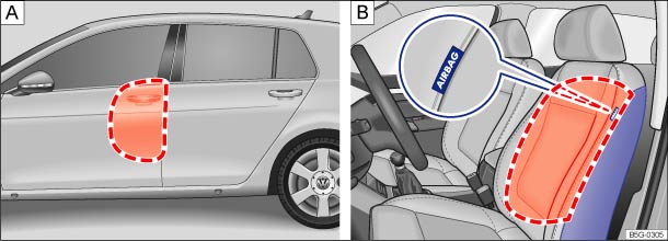 Fig. 72 On the driver side. : Location and deployment zone of the side airbags. : Location and deployment zone of the side airbags in the padding on the outboard side of the front seat backrests.Read and follow the introductory information and safety information first⇒Introduction to the subject
The side airbags are in the backrest padding of the driver and passenger seats ⇒ Fig. 72 . The general location is shown by the word AIRBAG. The area marked in red (dotted lines) indicates the deployment zone of the side airbags.
In a side collision, the side airbag in the seat backrest can deploy and help reduce the risk of injury to the driver or the front seat passenger.
The side airbags installed for the front seating positions have been designed and certified to help reduce the risk of injury that can be caused by airbags when they inflate, particularly when the occupant sitting next to it is not seated properly.
The side airbag for the front passenger seat can be used with properly installed child restraints. Always read and heed all important information and WARNINGS whenever using a child restraint in the vehicle: ⇒ Safety belts , ⇒ Airbag system , ⇒ Child safety and child restraints , and ⇒ .
When a side airbag deploys in a collision, a gas generator fills the side airbag between the vehicle occupant and the door. The side airbag system supplements the safety belts and can help to reduce the risk of injury to the occupant's upper torso.
In order to help provide this additional protection, the side airbag must inflate within the blink of an eye at very high speed and with great force. The supplemental side airbag could injure you if your seating position is not proper or upright or if items are in the area where the supplemental side airbag inflates. This applies especially to children ⇒ Child safety and child restraints .
The airbag system is monitored electronically to make sure it is working properly at all times. Every time you turn on the ignition, the airbag system indicator light will come on for a few seconds (function check).
The airbag system is not a substitute for your safety belt. Rather, it is part of the overall occupant restraint system in your vehicle ⇒ Adjusting the seating position , ⇒ Safety belts .
It is important to remember that the side airbag system is designed to help reduce the likelihood of serious injury. However, it is important to remember that a deploying airbag may also cause other injuries, such as swelling, bruising, friction burns, and abrasions. Also remember that side airbags will deploy only once and only in certain kinds of accidents. After the side airbag inflates, the system must be replaced. Your safety belts are always there to offer protection in those accidents in which side airbags are not supposed to deploy or when they have already deployed.
In some types of accidents the front airbags, Side Curtain Protection airbags and side airbags may be triggered together.
WarningAn inflating side airbag can cause serious or even fatal injury. Improperly wearing safety belts and improper seating positions increase the risk of serious personal injury and death whenever a vehicle is being used.
WarningImproper use, repair, or disassembly of the driver and front passenger seats can prevent side airbags from working properly and result in severe injuries.
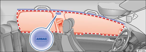 Fig. 73 On the left vehicle side (2-door vehicles only): Installation location and deployment zone of the Side Curtain Protection airbag.Read and follow the introductory information and safety information first⇒Introduction to the subject
The Side Curtain Protection airbags are in the header area on both sides of the vehicle ⇒ Fig. 73 . The general location is identified by the word AIRBAG. The red lines show the deployment zone of the Side Curtain Protection airbags.
The Side Curtain Protection airbags inflate downwards between the occupant and the side window on that side of the vehicle that is struck in certain side collisions ⇒ Fig. 73 . The Side Curtain Protection airbag system supplements the safety belts and can help to reduce the risk of injury for occupants' heads and upper torsos on the side of the vehicle that is struck in a side collision.
In order to help provide this additional protection, the Side Curtain Protection airbag must inflate within the blink of an eye at very high speed and with great force. The Side Curtain Protection airbag could injure you if your seating position is not proper or upright or if items are located in the area where the supplemental Side Curtain Protection airbag inflates. This applies especially to children ⇒ Child safety and child restraints .
The airbag system is monitored electronically to make sure it is working properly at all times. Every time you turn on the ignition, the airbag system indicator light will come on for a few seconds (function check).
The airbag system is not a substitute for your safety belt. Rather, it is part of the overall occupant restraint system in your vehicle ⇒ Adjusting the seating position , ⇒ Safety belts .
It is important to remember that the Side Curtain Protection airbag system is designed to help reduce the likelihood of serious injury. However, it is possible that a deployed Side Curtain Protection airbag may cause other injuries such as swelling, bruising, friction burns, and abrasions. Remember too, Side Curtain Protection airbags will deploy only once and only in certain kinds of accidents. Side Curtain Protection airbags that have deployed in a crash must be replaced. Your safety belts are always there to offer protection in those accidents in which Side Curtain Protection airbags are not supposed to deploy or when they have already deployed.
In some types of accidents the front, Side Curtain Protection and side airbags may be triggered together.
WarningAn inflating Side Curtain Protection airbag can cause serious or even fatal injury. Improperly wearing safety belts and improper seating positions increase the risk of serious personal injury and death whenever a vehicle is being used.
WarningThe airbag system can only be triggered once.
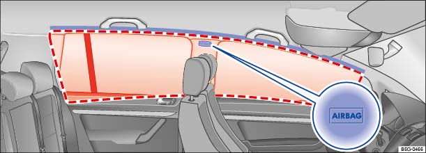 Fig. 74 On the left vehicle side (4-door vehicles only): Installation location and deployment zone of the Side Curtain Protection airbag.Read and follow the introductory information and safety information first⇒Introduction to the subject
The Side Curtain Protection airbags are in the header area on both sides of the vehicle ⇒ Fig. 74 . The general location is identified by the word AIRBAG. The red lines show the deployment zone of the Side Curtain Protection airbags. The Side Curtain Protection airbags contain features that provide ejection mitigation to help prevent vehicle occupants or parts of their bodies from being completely or partially ejected from the vehicle interior in certain side impacts and vehicle rollovers.
The Side Curtain Protection airbags inflate downwards between the occupant and the side window on that side of the vehicle that is struck in certain side collisions ⇒ Fig. 74 . The Side Curtain Protection airbag system supplements the safety belts and can help to reduce the risk of injury for occupants' heads and upper torsos on the side of the vehicle that is struck in a side collision. The Side Curtain Protection airbags also contain features to help prevent vehicle occupants or parts of their bodies from being completely or partially ejected from the vehicle interior in certain vehicle rollovers.
In order to help provide this additional protection, the Side Curtain Protection airbag must inflate within the blink of an eye at very high speed and with great force. The Side Curtain Protection airbag could injure you if your seating position is not proper or upright or if items are located in the area where the supplemental Side Curtain Protection airbag inflates. This applies especially to children ⇒ Child safety and child restraints .
The airbag system is monitored electronically to make sure it is working properly at all times. Every time you turn on the ignition, the airbag system indicator light will come on for a few seconds (function check).
The airbag system is not a substitute for your safety belt. Rather, it is part of the overall occupant restraint system in your vehicle ⇒ Adjusting the seating position , ⇒ Safety belts .
It is important to remember that the Side Curtain Protection airbag system is designed to help reduce the likelihood of serious injury. However, it is possible that a deployed Side Curtain Protection airbag may cause other injuries such as swelling, bruising, friction burns, and abrasions. Remember too, Side Curtain Protection airbags will deploy only once and only in certain kinds of accidents. Side Curtain Protection airbags that have deployed in a crash must be replaced. Your safety belts are always there to offer protection in those accidents in which Side Curtain Protection airbags are not supposed to deploy or when they have already deployed.
In some types of accidents the front, Side Curtain Protection and side airbags may be triggered together.
WarningAn inflating Side Curtain Protection airbag can cause serious or even fatal injury. Improperly wearing safety belts and improper seating positions increase the risk of serious personal injury and death whenever a vehicle is being used.
WarningThe airbag system can only be triggered once.
Introduction to the subjectIn this chapter you will find information on the following subjects:⇒ Child restraints – Overview ⇒ Child restraints and the Advanced Airbag System ⇒ Important safety instructions for using child restraints ⇒ Using a child restraint on the rear seat ⇒ Infant seats ⇒ Convertible child restraints ⇒ Booster seats and safety belts ⇒ Installing child restraints with a safety belt ⇒ Securing the child restraint with LATCH/UCRA lower universal anchorages ⇒ Securing a child restraint with the Top Tether strap ⇒ Sources of information about child restraints and their use
The physical principles of what happens when your vehicle is in a collision or other accident also apply to children ⇒ Safety belts . But unlike adults and teenagers, their muscles and bones are not fully developed. In many respects children are at greater risk of serious injury in accidents than are adults.
Because children's bodies are not fully developed, they must use restraint systems especially designed for their size, weight, and body structure. Many countries and all states of the United States and provinces of Canada have laws requiring the use of approved child restraint systems for infants and small children.
In a frontal crash at a speed of 20–35 mph (30–56 km/h), the forces acting on a 13 pound (6 kg) infant will be more than 20 times the weight of the child. This means the effective weight of the child would suddenly increase to more than 260 pounds (120 kg). Under these conditions, only an appropriate child restraint properly used can reduce the risk of serious injury. Child restraints, like adult safety belts, must be used properly to be effective. Used improperly, they can increase the risk of serious injury in an accident.
All children, especially those 12 years and younger, must always ride in the back seat properly restrained for their age and size. If you must install a child restraint on the front passenger seat in exceptional circumstances, be sure to read and heed the important information and warnings in the section of this Manual that begins on ⇒ Child restraints and the Advanced Airbag System . Infants and other children who are properly restrained in an appropriate child restraint that is for their size and age can benefit from the protection that supplemental side airbags provide in some kinds of crashes.
For more information, please see information provided by the:
Consult the child restraint manufacturer's instructions to be sure the seat is right for your child's size ⇒ Sources of information about child restraints and their use . Please be sure to read and heed all of the important information and WARNINGS about child safety, Advanced Airbags, and the installation of child restraints in this Manual.
There is a lot you need to know about the Advanced Airbags in your vehicle and how they work when infants and children in child restraints are on the front passenger seat. Because of the large amount of important information, we cannot repeat it all here. We urge you to read the detailed information in this Manual about airbags and the Advanced Airbag System in your vehicle and the very important information about transporting children on the front passenger seat. Please be sure to heed the WARNINGS - they are extremely important for your safety and the safety of your passengers, especially infants and small children.
Danger!Children on the front seat of any car, even with Advanced Airbags, can be seriously injured or even killed when an airbag inflates.
WarningAccident statistics have shown that children are generally safer in the rear seat area than in the front seating position. Always restrain any child age 12 and under in the rear.
WarningForward-facing child restraints installed on the front passenger seat may interfere with the deployment of the airbag and cause serious personal injury to the child.
Always replace child restraints that were installed in a vehicle during a crash. Damage to a child restraint that is not visible could cause it to fail in another collision situation.
Read and follow the introductory information and safety information first⇒Introduction to the subject
All children and especially infants must be properly restrained in a child restraint appropriate for their size and age whenever riding in a vehicle. Their safety also requires that the child restraint be properly installed. There are many car seat choices on the market. You can use the information below to help you choose a car seat that best meets your child’s needs.
| Type of child restraint | Applies to |
|---|---|
| Rear-facing child restraint |
Birth to 12 months: Your child under age 1 should always ride in a rear-facing car seat. There are different types of rear-facing car seats: – Infant-only seats can only be used rear-facing. – Convertible and all-in-one car seats typically have higher height and weight limits for the rear-facing position, allowing you to keep your child rear-facing for a longer period of time. |
| Rear-facing child restraint before moving to a forward-facing child restraint | 1–3 years: Keep your child rear-facing as long as possible. It’s the best way to keep him or her safe. Your child should remain in a rear-facing car seat until he or she reaches the top height or weight limit allowed by the car seat’s manufacturer. Once your child outgrows the rear-facing car seat, your child is ready to travel in a forward-facing car seat with a harness and tether. |
| Forward-facing child restraint | 4–7 years: Keep your child in a forward-facing car seat with a harness and tether until he or she reaches the top height or weight limit allowed by the car seat’s manufacturer. Once your child outgrows the forward-facing car seat with a harness, it’s time to travel in a booster seat, but still in the back seat. |
| Booster seat | 7–12 years: Keep your child in a booster seat until he or she is big enough to fit in a seat belt properly. For a seat belt to fit properly, the lap belt must lie snugly across the upper thighs, not the stomach. The shoulder belt should lie snugly across the shoulder and chest and not cross the neck or face. Remember: your child should still ride in the back seat because it’s safer there. |
Child restraints are designed to be secured to the vehicle with the lap belt portion of the 3 point lap and shoulder belt installed for the passenger seats. The outboard rear seating positions also have special fixtures for child restraints that can be used with LATCH/UCRA lower universal anchorages. Many child restraints use also require the use of a top tether strap. The top tether strap reduces the forward movement of the child restraint in a crash, to help reduce the risk of head injury if the child hits the vehicle interior.
The LATCH/UCRA lower universal anchorage attachment points are on the lower part of the rear seat backrest for the 2 outboard seating positions. Each lower universal anchorage point has a cover. The circular markings on the covers help you to locate the lower anchorages⇒ Securing the child restraint with LATCH/UCRA lower universal anchorages ⇒ Fig. 80 .
The top tether anchorages are behind each of the rear seating positions⇒ Securing a child restraint with the Top Tether strap ⇒ Fig. 83 .
Read and follow the introductory information and safety information first⇒Introduction to the subject
Your vehicle is equipped with a front Advanced Airbag System that complies with United States Federal Motor Vehicle Safety Standard (FMVSS) 208 and with Canada Motor Vehicle Safety Standard (CMVSS) 208 as applicable at the time your vehicle was manufactured.
The Advanced Airbag System in your vehicle has been certified to meet the low risk requirements for 3 to 6 year-old children (as defined in the standard) on the passenger side and small adults on the driver side. Low risk deployment occurs in those crashes that take place at lower decelerations as defined in the electronic control unit. The low risk deployment criteria are intended to reduce the risk of injury through interaction with the airbag that can occur in these collisions, for example, by being too close to the steering wheel or instrument panel when the airbag inflates.
In addition, the system has been certified to comply with the suppression requirements of the Safety Standard, to turn off the front airbag automatically for infants up to 12 months who are restrained on the front passenger seat in child restraints that are listed in the Standard.
Even though your vehicle is equipped with an Advanced Airbag System, all children, especially those 12 years and younger, must always ride in the back seat properly restrained for their age and size. The airbag on the passenger side makes the front seat a potentially dangerous place for a child to ride. The front seat is not the safest place for a child in a forward-facing child restraint. It is a very dangerous place for an infant or a larger child in a rearward-facing seat.
The vehicle's Advanced Airbag System has a capacitive passenger detection system in the front passenger seat cushion that can detect the presence of a baby or a child in a child restraint system on this seat.
The capacitive passenger detection system measures the capacitance of the child and the child restraint and a child blanket on the front passenger seat. The capacitance due to the presence of a child, a child restraint, and a baby blanket on the front passenger seat is related to the child restraint system resting on the seat. The capacitance of a child restraint system varies depending on the type of system and specific make and model.
The electrical capacitance of the various types, makes, and models of child restraints specified by the U.S. National Highway Traffic Safety Administration (NHTSA) in the relevant safety standard are stored in the Advanced Airbag System control unit together with the capacitances typical of infants and a 1 year-old child. When a child restraint is used on the front passenger seat with a typical 1 year-old infant, the Advanced Airbag System compares the capacitance measured by the capacitive passenger detection system with the data stored in the electronic control unit.
No matter what child restraint you use, make sure that it has been certified to meet U.S. Federal Motor Vehicle Safety Standard 213 (FMVSS 213) or, if you live in Canada, Canada Motor Vehicle Safety Standard 213 (CMVSS 213). Also make sure that the child restraint you are using has been certified by its manufacturer for use with an airbag. Always be sure that the child restraint is properly installed at one of the rear seating positions. If in exceptional circumstances you must use it on the front passenger seat, carefully read all of the information on child safety and Advanced Airbags and heed all of the applicable WARNINGS. Make certain that the child restraint is correctly recognized by the capacitive passenger detection system inside the front passenger seat, that the passenger front airbag is switched off, and that the airbag status is always correctly signaled by the PASSENGER AIR BAG
light.
Many types and models of child restraints have been available over the years, new models are introduced regularly incorporating new and improved designs and older models are taken out of production. Child restraints are not standardized. Child restraints of the same type typically have different weights and sizes and different footprints, the size and shape of the bottom of the child restraint that sits on the seat, when they are installed on a vehicle seat. These differences make it virtually impossible to certify compliance with the requirements for Advanced Airbags with each and every child restraint that has ever been sold in the past or will be sold over the course of the useful life of your vehicle.
For this reason, the United States National Highway Traffic Safety Administration has published a list of specific types, makes and models of child restraints that must be used to certify compliance of the Advanced Airbag System in your vehicle with the suppression requirements of Federal Motor Vehicle Safety Standard 208. These child restraints are:
| Model | Manufactured on or after |
|---|---|
| Angel Guard Angel Ride AA2403FOF | September 25, 2007 |
| Model | Manufactured on or after |
|---|---|
| Century Smart Fit 4543 | December 1, 1999 |
| Cosco Arriva 22-013 PAW and base 22-999 WHO | September 25, 2007 |
| Evenflo Discovery Adjust Right 212 | December 1, 1999 |
| Graco Infant 8457 | December 1, 1999 |
| Graco Snugride | September 25, 2007 |
| Peg Perego Primo Viaggio SIP IMUN00US | September 25, 2007 |
| Model | Manufactured on or after |
|---|---|
| Britax Roundabout E9L02xx | September 25, 2007 |
| Cosco Touriva 02519 | December 1, 1999 |
| Cosco Summit Deluxe High Back Booster 22-262 | September 25, 2007 |
| Cosco High Back Booster 22-209 | September 25, 2007 |
| Evenflo Tribute V 379xxxx | September 25, 2007 |
| Evenflo Medallion 254 | December 1, 1999 |
| Evenflo Generations 352xxxx | September 25, 2007 |
| Graco ComfortSport | September 25, 2007 |
| Graco Toddler SafeSeat Step 2 | September 25, 2007 |
| Graco Platinum Cargo | September 25, 2007 |
WarningTo reduce the risk of serious injury, always make sure that the PASSENGER AIR BAG
light comes on and stays on whenever a child restraint is installed on the front passenger seat and the ignition is switched on.
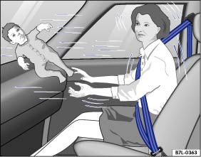 Fig. 75 Never let babies or older children ride in a vehicle while sitting on the lap of another passenger.Read and follow the introductory information and safety information first⇒Introduction to the subject
Proper use of child restraints greatly reduces the risk of injury in a collision or other kind of accident!
All children, especially those 12 years and younger, must always ride in the back seat properly restrained for their age and size.
Always use the right child restraint for each child and always use it properly.
Always carefully follow the child restraint manufacturer's instructions on how to route the safety belt properly through the child restraint and how to restrain the child in the child restraint.
When using the vehicle safety belt to install a child restraint, you must activate the switchable locking feature on the safety belt to help prevent the child restraint from moving ⇒ Installing child restraints with a safety belt .
Push the child restraint down with your full weight to get the safety belt really tight so that the seat cannot move forward or sideways more than about 1 inch (2.5 cm).
If you must install a child restraint on the front passenger seat in exceptional circumstances, be sure to read and heed the important information and warnings in the section of this Manual that begins on ⇒ Child restraints and the Advanced Airbag System .
Set the safety belt upper anchorage for the front passenger seat so that the available safety belt is long enough to properly install the child restraint. Always follow the child restraint manufacturer's installation instructions ⇒ .
Move the front passenger seat to the highest position in the seat's up and down adjustment range and to the rearmost position in the seat's fore and aft adjustment range, as far away from the airbag as possible before installing the forward-facing child restraint and make sure the backrest is in the upright position ⇒ .
When using the vehicle safety belt to install a child restraint, you must activate the switchable locking feature on the safety belt to help prevent the child restraint from moving ⇒ Using a child restraint on the rear seat . Always follow the child restraint manufacturer’s instructions when installing a child restraint.
Do not use the switchable locking feature when using the vehicle's safety belt to restrain a child on a booster seat.
Always remember: Even though your vehicle is equipped with an Advanced Airbag System, all children, especially those 12 years and younger, must always ride in the back seat properly restrained for their age and size.
Danger!Never install rearward-facing child restraints or infant carriers on the front passenger seat.
WarningNot using a child restraint, using the wrong child restraint, or improperly installing a child restraint increases the risk of serious personal injury and death in a collision or other emergency situation.
WarningForward-facing child restraints installed on the front passenger's seat can interfere with the airbag when it inflates and cause serious injury to the child.
WarningTo reduce the risk of serious injury, always make sure that the PASSENGER AIR BAG
light comes on and stays on whenever a child restraint is installed on the front passenger seat and the ignition is switched on.
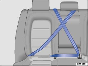 Fig. 76 Keep unused safety belts away from children in child restraints.Read and follow the introductory information and safety information first⇒Introduction to the subject
You must take special precautions when installing a LATCH/UCRA child restraint behind the front passenger or driver seats. Always route the center safety belt and the unused safety belt for the seating position where the child restraint is being installed securely out of the child’s reach. Securing the safety belts will help prevent a child from playing with an unused safety belt and becoming entangled with it ⇒ Fig. 76 .
When routing a safety belt for an outboard seating position, do not activate the switchable locking feature, otherwise it will be very difficult to wind the safety belt back into its normal position. You should not hear a clicking sound when the safety belt retracts.
When routing a center seat safety belt, you must activate the switchable locking feature. When the safety belt retracts, a clicking sound indicates that the switchable locking feature is active.
When a child safety seat is secured on the rear bench, adjust the position of the front seat to provide the child with sufficient space. Therefore, adjust the front seat to the size of the child safety seat and the child. Consider the proper seating position of the passenger ⇒ .
When child restraints are not needed, be sure to remove the safety belt(s) from around the head restraint(s), unbuckle the center safety belt, and return all safety belts to their normal stored positions so that they will be available for regular use.
WarningA child in a child restraint installed with the LATCH/UCRA lower universal anchorages or with the standard safety belt on the rear seat may play with unused rear seat safety belts and become entangled, resulting in serious personal injury and even death.
Note
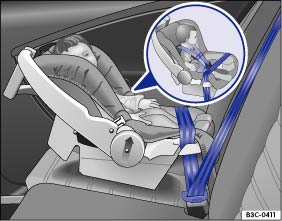 Fig. 77 Rearward-facing infant seat properly installed on the rear seat.Read and follow the introductory information and safety information first⇒Introduction to the subject
The American Academy of Pediatrics (AAP) recommends that all infants should ride in rear-facing car safety seats (in which the child faces the back of the vehicle) starting with their first ride home from the hospital. All infants and toddlers (generally up to age 3) should ride in a rear-facing car safety seat as long as possible – or until they reach the highest weight or height allowed by their child restraint’s manufacturer. These infant seats support the baby's back, neck and head in a collision. Rear-facing child restraints can be used safely only on the rear seat of the vehicle ⇒ Fig. 77 .
Before installing a child restraint on the front passenger seat, be sure to follow the special instructions and heed the warnings ⇒ Child restraints and the Advanced Airbag System and ⇒ The dangers of using child restraints on the front seat .
The airbag on the passenger side makes the front seat a potentially dangerous place for a child to ride. The front seat is not the safest place for a child in a forward-facing child restraint. It is a very dangerous place for an infant or a larger child in a rearward-facing seat.
You must take special precautions when installing a child restraint with the vehicle safety belt or with LATCH/UCRA lower universal anchorages behind the front passenger seat or behind the driver seat. Always route the center safety belt and the unused safety belt for the seating position where the child restraint is being installed securely out of the child’s reach. Securing the safety belts will help prevent a child from playing with an unused safety belt and becoming entangled with it ⇒ Using a child restraint on the rear seat , ⇒ Fig. 76 .
Danger!Not using a child restraint, using the wrong child restraint or improperly installing a child restraint increases the risk of serious personal injury and death in a collision or other emergency situation.
WarningA child in a child restraint installed with the LATCH/UCRA lower universal anchorages or with the standard safety belt on the rear seat may play with unused rear seat safety belts and become entangled, resulting in serious personal injury and even death.
Note
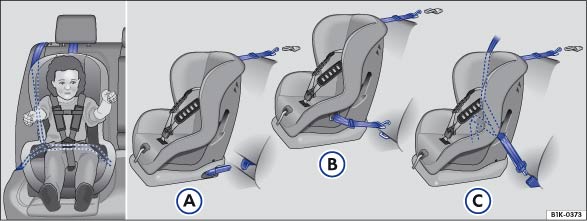 Fig. 78 Some child restraints have lower anchors and a top tether. Figures Ⓐ and Ⓑ show how to correctly install a LATCH/UCRA seat. Figure Ⓒ shows the set up of a seat using the vehicle's safety belt system.Read and follow the introductory information and safety information first⇒Introduction to the subject
Children between 1 and about 7 years old must always be properly restrained in a child restraint certified for their size and weight ⇒ Fig. 78 .
Once your child outgrows the rear-facing car seat (generally up to age 3), your child is ready to travel in a forward-facing car seat with a harness. Keep your child in a forward-facing car seat with a harness until he or she reaches the top height or weight limit allowed by your car seat’s manufacturer.
Before installing a child restraint on the front passenger seat, be sure to follow the special instructions and heed the warnings ⇒ Child restraints and the Advanced Airbag System and ⇒ The dangers of using child restraints on the front seat .
The airbag on the passenger side makes the front seat a potentially dangerous place for a child to ride. The front seat is not the safest place for a child in a forward-facing child restraint. It is a very dangerous place for an infant or a larger child in a rearward-facing seat.
You must take special precautions when installing a child restraint with the vehicle safety belt or with LATCH/UCRA lower universal anchorages behind the front passenger seat or behind the driver seat. Always route the center safety belt and the unused safety belt for the seating position where the child restraint is being installed securely out of the child’s reach. Securing the safety belts will help prevent a child from playing with an unused safety belt and becoming entangled with it ⇒ Using a child restraint on the rear seat , ⇒ Fig. 76 .
Danger!Not using a child restraint, using the wrong child restraint or improperly installing a child restraint increases the risk of serious personal injury and death in a collision or other emergency situation.
WarningAn improperly installed child restraint can interfere with the airbag as it deploys and seriously injure or even kill the child – even with an Advanced Airbag System.
WarningA child in a child restraint installed with the LATCH/UCRA lower universal anchorages or with the standard safety belt on the rear seat may play with unused rear seat safety belts and become entangled, resulting in serious personal injury and even death.
Note
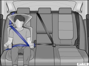 Fig. 79 Child properly restrained in a booster seat on the rear seat.Read and follow the introductory information and safety information first⇒Introduction to the subject
Children between about 8 to 12 years old are best protected in child safety seats designed for their age and weight ⇒ Fig. 79 . Experts say that the skeletal structure, particularly the pelvis, of these children is not fully developed, and they must not use the vehicle safety belts without a suitable child restraint.
The vehicle's safety belts alone will not fit most children until they are at least 4 ft. 9 in. (57 inches / 1.45 meters) tall. Booster seats raise these children up so that the safety belt will pass properly over the strong parts of their bodies and the safety belt can help protect them in a collision.
Children who are at least 4 ft. 9 in. (57 inches / 1.45 meters) tall can generally use the vehicle's 3 point lap and shoulder belts. Never use the lap belt portion of the vehicle's safety belt alone to restrain any child, regardless of how big the child is. Always remember that children do not have the pronounced pelvic structure required for the proper function of lap belt portion of the vehicle's 3 point lap and shoulder belts. The child's safety absolutely requires that a lap belt portion of the safety belt be fastened snugly across the upper thighs. Never let the lap belt portion of the safety belt pass over the child's stomach or abdomen.
It is usually best to put these children in appropriate booster seats and keep them in a booster seat until they are big enough to fit in a safety belt properly. Be sure the booster seat meets all applicable safety standards.
Booster seats raise the seating position of the child and reposition both the lap and shoulder parts of the safety belt so that they pass across the child's body in the right places. The routing of the belt over the child's body is very important for the child's protection, whether or not a booster seat is used. Children age 12 and under must always ride in the rear seat.
Keep your child in a booster seat until he or she is at least 4 ft. 9 in. (57 inches / 1.45 meters) tall AND your child is:
The way the safety belt passes over the child’s body is important for their safety and protection in a crash. Always make sure you child can wear the safety belt properly:
Always check belt fit on the child in every vehicle. A booster seat may be needed in some vehicles and not in others. If the seat belt does not fit properly, the child must continue to use a booster seat. Regardless of whether the child is using a booster or is able to properly wear the standard safety belt properly without a booster seat, keep your child in the back seat. Accident statistics show that children are safer on the rear seat than on the front seat.
In a collision, airbags must inflate within a blink of an eye and with considerable force. In order to do its job, the airbag needs room to inflate so that it will be there to protect the occupant as the occupant moves forward into the airbag.
Even Advanced Airbags can injure children when they inflate. A vehicle occupant who is out of position and too close to the airbag gets in the way of an inflating airbag. When an occupant is too close, he or she will be struck violently and will receive serious or possibly even fatal injuries.
In order for the airbag to offer protection, it is important that all vehicle occupants, especially children, who must be in the front seat under exceptional circumstances, be properly restrained and as far away from the airbag as possible. By keeping room between the child's body and the front of the passenger compartment, the airbag can inflate completely and provide supplemental protection in certain frontal collisions.
You must take special precautions when installing a booster seat with the vehicle safety belt behind the front passenger seat or behind the driver seat. Always route and secure the unused center safety belt to help prevent a child from playing with the unused safety belt and becoming entangled in it ⇒ Using a child restraint on the rear seat , ⇒ Fig. 76 .
WarningNot using a booster seat, using the booster seat improperly, incorrectly installing a booster seat or using the vehicle safety belt improperly increases the risk of serious personal injury and death in a collision or other emergency situation. To help reduce the risk of serious personal injury and/or death:
WarningA child in a child restraint installed with the LATCH/UCRA lower universal anchorages or with the standard safety belt on the rear seat may play with unused rear seat safety belts and become entangled, resulting in serious personal injury and even death.
Read and follow the introductory information and safety information first⇒Introduction to the subject
Safety belts for the rear seats and the front passenger seat must be locked with the switchable locking feature to properly secure child restraints.
Child restraints are designed to be secured to the vehicle with the lap belt portion of the 3 point lap and shoulder belt installed for the passenger seats. The outboard rear seating positions also have special fixtures for child restraints that can be used with LATCH/UCRA lower universal anchorages.
Regardless of the kind of child restraint that you use, always make sure that the child restraint is properly secured in the vehicle; otherwise the child could be seriously injured in a crash. Always follow legal requirements regarding the installation of child restraints.
Whenever a child restraint (except a booster seat) is installed with a safety belt, the safety belt must be locked so that the safety belt webbing cannot unreel. The switchable locking feature lets you lock the belt so that a child restraint can be properly installed and, for example, so that it cannot tip to the side when the vehicle goes around a corner.
Place the child restraint on a seat, preferably on a rear seat⇒ .
Always carefully follow the child restraint manufacturer's instructions when installing a child restraint in your vehicle ⇒ .
Always carefully follow the child restraint manufacturer's instructions when installing a child restraint in your vehicle ⇒ .
Place the child restraint on a seat, preferably on a rear seat⇒ . If in exceptional circumstances you must install the child restraint on the front seat, be sure to follow the special instructions and heed the WARNINGS below.
Always remember: Even though your vehicle is equipped with an Advanced Airbag System, all children, especially those 12 years and younger, must always ride in the back seat properly restrained for their age and size.
Always remember: Even though your vehicle is equipped with an Advanced Airbag System, all children, especially those 12 years and younger, must always ride in the back seat properly restrained for their age and size.
The switchable locking feature for child restraints will be deactivated automatically when the belt is wound all the way back into the retractor.
Always let the safety belt retract completely into its stowed position. The safety belt can now be used as an ordinary safety belt without the switchable locking feature for child restraints.
If the switchable locking feature should be activated inadvertently, the safety belt must be unfastened and guided completely back into its stowed position to deactivate this feature. If the switchable locking feature is not deactivated, the safety belt will gradually become tighter and uncomfortable to wear.
WarningUsing the wrong child restraint or an improperly installed child restraint can cause serious personal injury or death in an accident.
WarningImproperly installed child restraints increase the risk of serious personal injury and death in a collision.
NoteWhen installing a child restraint, be careful not to get the belt caught in the structure of the child restraint and become damaged, especially when the switchable locking feature has been activated.
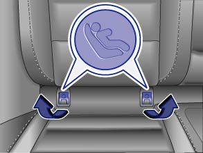 Fig. 80 On the rear outboard seat backrests: Markings on the covers of the LATCH/UCRA lower universal anchorages.
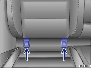 Fig. 81 On the rear outboard seat backrests: LATCH/UCRA lower universal anchorages (covers removed).Read and follow the introductory information and safety information first⇒Introduction to the subject
LATCH is used in the United States for Lower Anchors and Tethers for Children. In Canada, Universal Child Restraint Anchorages (UCRA) is used to describe the combination of top tether straps and lower anchorages.
All child restraints manufactured after September 1, 1999 must have LATCH/UCRA lower universal anchorages.
The LATCH/UCRA lower universal anchorage attachment points are on the lower part of the rear seat backrest for the 2 outboard seating positions. Each lower universal anchorage point has a cover. The circular markings on the covers help you to locate the lower anchorages ⇒ Fig. 80 . Remove the covers to access the lower anchorage points ⇒ Fig. 81 (arrows).
LATCH/UCRA lower universal anchorages secure the child restraint system in the seat without using the vehicle's safety belts. Anchorages provide a secure and easy-to-use attachment and minimize the possibility of improper child restraint installation.
Remember that the LATCH/UCRA lower universal anchorage points are only intended for installation and attachment of child restraints specifically certified for use with these lower universal anchorages. Child restraints that are not equipped with the LATCH/UCRA lower universal anchorage attachments can still be installed with vehicle safety belts according to the child restraint manufacturer's instructions. You must never mount 2 child restraint systems to one LATCH/UCRA lower universal anchorage point at the same time. For instance, you must not install a child restraint with LATCH/UCRA lower universal anchorage points on one of the outboard seating positions and then use the inboard anchorage to also install a child restraint in the center of the rear seat that itself is not equipped with LATCH/UCRA lower universal anchorage points.
There are 2 ways to attach an appropriate child restraint to the LATCH/UCRA lower universal anchorages:
Depending on your vehicle's seats, you may want to use guidance fixtures when installing a child restraint that has rigid mountings. Installation with guidance fixtures is easier and protects the upholstery. Guidance fixtures are included with the child restraint in some cases. If not, they can be purchased from an authorized Volkswagen dealer or an authorized Volkswagen Service Facility. The guidance fixtures must be installed in accordance with the manufacturer's instructions at the anchorage points between the seat cushion and the seat backrest.
You must take special precautions when installing a child restraint with the vehicle safety belt or with LATCH/UCRA lower universal anchorages behind the front passenger seat or behind the driver seat. Always route the unused center seat safety belt and the unused safety belt for the seating position where the LATCH/UCRA child restraint is being installed around the rear head restraint behind the child restraint to help prevent a child from playing with the unused belt and becoming entangled in it.
WarningImproper use of the LATCH/UCRA system can increase the risk of serious personal injury and death in an accident.
Note
Be careful not to activate the switchable locking retractor when routing the safety belts around the head restraints. Only pull the safety belt out far enough to allow you to route the belt around the head restraint.
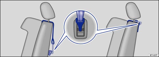 Fig. 82 Example of a mounted upper tether strap: The top tether strap reduces the forward movement of the child restraint in a crash, to help reduce the risk of head injury if the child hits the vehicle interior.
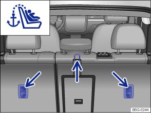 Fig. 83 Anchorages for the top tether strap on the back of the rear seat.Read and follow the introductory information and safety information first⇒Introduction to the subject
.WarningImproper installation of child restraints will increase the risk of injury and death in a crash.
NoteIf you leave the child restraint with the tether strap firmly installed for several days, this could leave a mark on the upholstery on the seat cushion and backrest in the area where the tether strap was installed. The upholstery would also be permanently stretched around the tether strap. This applies especially to leather seats.
Read and follow the introductory information and safety information first⇒Introduction to the subject
The following are some sources of additional information about child restraint selection, installation and use:
Safety authorities advise that the best child safety seat is the one that fits your child and fits in your vehicle, and that you will use correctly and consistently.
Try before you buy!
1-800-333-03711-613-998-8616 (Ottawa)http://www.tc.gc.ca/roadsafety
1-888-327-4236 (TTY: 1-800-424-9153)http://www.nhtsa.govhttp://www.safercar.gov
1-202-662-0600http://www.safekids.org
1-800-745-SAFE or 1-800-745-7233 (English)1-800-747-SANO or 1-800-747-7266 (Spanish)http://www.carseat.org
1-800-822-8987
Introduction to the subjectIn this chapter you will find information on the following subjects:⇒ Indicator lights ⇒ Turn signal lever and high beam switch ⇒ Switching lights on and off ⇒ Lights and vision – features ⇒ Coming Home/Leaving Home features (orientation lighting) ⇒ Light Assist ⇒ Instrument panel lighting and headlight range adjustment ⇒ Interior and reading lights
Always obey local vehicle lighting laws.
The driver is always responsible for the correct headlight settings.
WarningCrashes and other accidents can happen when you cannot see the road ahead and when you cannot be seen by other motorists.
WarningHeadlights that are aimed too high and improper use of the headlight flasher or high beams can blind and distract other drivers. This can lead to a crash and serious personal injuries.
Read and follow the introductory information and safety information first⇒Introduction to the subject
| Lights up | Possible cause | Proper response |
|---|---|---|
|
|
Central caution light. | Read and follow the text messages in the instrument cluster display. |
|
|
One or more driving lights not working, excluding the Adaptive Front Lighting System (AFS). | Replace the burned out bulb ⇒ Replacing light bulbs . If all light bulbs are OK, see an authorized Volkswagen dealer or authorized Volkswagen Service Facility. |
|
|
Left or right turn signal. The indicator light blinks twice as fast if a turn signal is not working on the vehicle or the trailer. |
Check the turn signals on the vehicle and the trailer. |
|
|
High beams switched on or headlight flashers in use. | ⇒ Turn signal lever and high beam switch . |
|
|
Light Assist high beam control switched on. | ⇒ Light Assist . |
When the ignition is switched on, several warning and indicator lights come on briefly for a function check. They go out after a few seconds.
| Lights up | Possible cause |
|---|---|
|
|
The fog lights are switched on ⇒ Switching lights on and off |
|
|
The parking lights are switched on ⇒ Switching lights on and off . |
|
|
The automatic headlights and, if applicable, the daytime running lights are switched on ⇒ Switching lights on and off . |
WarningFailure to heed warning lights and instrument cluster text messages can cause the vehicle to break down in traffic and result in a collision and serious personal injury.
NoteFailure to heed warning lights or text WARNINGS can result in vehicle damage.High Intensity Discharge (HID) headlights provide bright, uniform lighting to help you see and be seen. The light comes from an electric arc between two electrodes in the gas-filled bulb. Over time, the electrodes can wear down and the gap between them will get wider. The HID lamp’s control unit then increases the voltage to keep the arc’s brightness constant. However, the commonly called “Xenon” bulbs will also ultimately burn out. Before they burn out, HID lamps can flicker. A message will then appear in the MFD. This is your reminder to see an authorized Volkswagen dealer or an authorized Volkswagen Service facility to check the headlights.
Displayed in color on an instrument cluster with color display.
A separate display appears in the instrument cluster if there is an AFS malfunction.
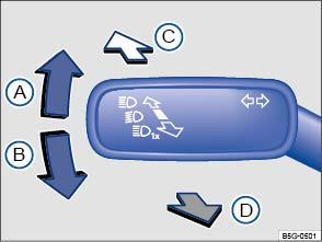 Fig. 84 On the left side of the steering column: Turn signal lever and high beam switch.Read and follow the introductory information and safety information first⇒Introduction to the subject
Move the lever to the desired position
Right turn signal.Left turn signal.Switching high beams on ⇒ . An indicator light  Switching the high beams off and operating the headlight flasher. The headlight flasher turns on the high beams as long as the lever is pulled and manually held in the pulled position. The indicator light
 Move the lever back to the home position to turn the selected feature off.
To use the convenience turn signal, move the lever up or down slightly, just to the point of resistance and then release it. If you have the convenience turn signal switched on, the turn signals and the turn signal indicator flash 3 times. If it is switched off, they flash as long as you hold the lever up or down, and go out when you release the lever.
The convenience turn signal can be switched on and off in the Infotainment system by pressing the button followed by the
and Lights function keys ⇒ Menu and system settings .
WarningImproper use of high beams can distract and blind others, causing accidents and serious injuries.The turn signal light works only when the ignition is switched on. The emergency flasher works even when the ignition is switched off ⇒ In an emergency .The indicator light flashes twice as fast if a turn signal bulb is burned out.High beams can only be switched on when the low beams are on.
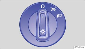 Fig. 85 Headlight switch next to the steering wheel.
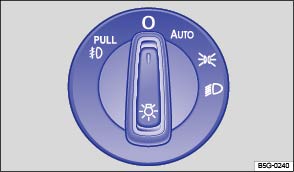 Fig. 86 Headlight switch next to the steering wheel (with fog lights and automatic headlights, if equipped).Read and follow the introductory information and safety information first⇒Introduction to the subject
| Adjust the light switch to the desired position ⇒ Fig. 85 or ⇒ Fig. 86 : | ||
|---|---|---|
| Symbol | When the ignition is switched off | When the ignition is switched on |
|
|
Fog lights and low beams switched off. | Headlights off, daytime running lights (DRL) on. |
|
|
Orientation lighting may be switched on. | Automatic headlights active; DRL on. |
|
|
Low beams switched off. The DRL may stay on. The length of time they stay on depends on the vehicle battery charge. | Headlights and taillights switched on. |
|
|
Parking lights and taillights switched on. | Parking lights, DRL, and taillights switched on. |
|
|
Fog lights switched off. The DRL may stay on for some time. | Headlights and fog lights switched on. |
The indicator light in the headlight switch shows that the fog lights are switched on.
In the following situation, a warning chime will sound if you take the key out of the ignition and open the driver door. This is to remind you that lights are still on.
WarningDaytime running lights and parking lights are not bright enough to let you see ahead or be seen by others when it is dark.
In cool or humid weather, the insides of the headlights, the rear lights, and turn signals can temporarily fog up. This is normal and does not affect the service life of the vehicle's lighting system.
Read and follow the introductory information and safety information first⇒Introduction to the subject
If the ignition is switched off and the vehicle is locked from the outside with the headlight switch in the position, the parking lights in both headlights come on together with both taillights.
If the headlight switch is in the position before you switch off the ignition, and you do not switch the parking lights off when leaving the vehicle, the parking lights stay on for about 30 minutes before automatically switching off. This feature helps prevent the parking lights from draining the vehicle battery if they were left on unintentionally.
If you move the headlight switch to the position after switching off the ignition, the parking lights stay on when you leave the vehicle and will not switch off automatically ⇒
.
Separate lamps are installed in the headlights or in the front bumper for the daytime running lights (DRL).
The daytime running lights are switched on whenever the ignition is switched on and the light switch is in position ,
, or
.
When the daytime running lights are switched on, only these separate lamps come on if the headlight switch is in position or
⇒
.
If the light switch is in position , a low-light sensor switches the low beams as well as the instrument and switch lighting on and off automatically.
Some models are equipped with a daytime running lights (DRL) parking feature that switches the daytime running lights off when the parking brake is engaged and the ignition is switched on.
| Function | Action |
|---|---|
| Switching the DRL off: |
– Switch the ignition on. – Turn the light switch to the – Set the parking brake. |
| Switching the DRL back on: | – Release the parking brake. |
Your vehicle may have fog lights under the front bumper, which on some models are also static cornering lights. On some models the static cornering lights may be integrated in the headlights. At speeds below about 25 mph (40 km/h), the light on one side of the vehicle will come on automatically when you turn a corner. If you turn to the right, the right fog light comes on; turn left and the left fog light comes on. The light dims and goes out when the steering wheel is straightened out again.
When you move the selector lever to Reverse (R), the static cornering lights on both sides of the vehicle may come on so that you can see the area around the vehicle better when backing up.
The static cornering lights work only when the headlights are on. If you are using automatic headlights (headlight switch in the position ⇒ Fig. 86 ), they work only when the headlights have been automatically switched on. The static cornering lights do not come on when the headlight switch is in the
position or when the fog lights themselves have been switched on ⇒ Switching lights on and off .
Your vehicle may be equipped with automatic headlights (), which are a convenience feature only and cannot always recognize all lighting and driving situations.
If the light switch is in the position, both vehicle lighting and instrument and switch lighting are automatically switched on and off in the following situations ⇒
:
| Automatic activation: | Automatic deactivation: |
|---|---|
| If the low-light sensor registers darkness, for example, when driving through a tunnel or at dusk. | If sufficient brightness is registered. |
| If the rain sensor recognizes rain and switches the windshield wipers on. | If the windshield wipers have not moved for several minutes. |
You can adjust the level of darkness the vehicle must register before automatically switching on the headlights in the Infotainment system by pressing the button followed by the function keys
and Lights⇒ Menu and system settings . You can also turn the automatic activation of the headlights with the rain sensors on and off via this menu.
The Adaptive Front Lighting System (AFS) works only with the low beams switched on and only at speeds above about 6 mph (10 km/h). The swivel-mounted lamps automatically improve road illumination during cornering.
In vehicles with Driving Mode Selection, the selected driving mode can affect the turning of the lights ⇒ Driving Mode Selection .
In some models, the headlights will turn independently, even when driving straight ahead. They can adjust according to the weather conditions and the speed of the vehicle to better light up the road ahead. The bulbs return to their original position after a short period of time, depending on the vehicle speed.
On vehicles equipped with AFS, the feature can be switched on and off in the Infotainment system by pressing the button followed by the
and Lights function keys ⇒ Menu and system settings .
WarningCrashes and other accidents can happen when you cannot see the road ahead and when you cannot be seen by other motorists.
NoteLeaving the parking lights on when the ignition is switched off can drain the vehicle battery.In cool or humid weather, the insides of the headlights, the rear lights, and turn signals can temporarily fog up. This is normal and does not affect the service life of the vehicle's lighting system.
Read and follow the introductory information and safety information first⇒Introduction to the subject
Your vehicle may be equipped with Coming Home/Leaving Home features, which are controlled automatically by a low-light sensor.
| Coming Home | Action |
|---|---|
| Switch on: |
– Switch off the ignition. The Coming Home feature is switched on when the headlight switch is in the The delay period starts once the last vehicle door or the trunk lid is closed. |
| Switch off: |
– Automatically after delay period is over. – Automatically, if a vehicle door or the trunk lid is still open about 30 seconds after activation. – Turn light switch to the – Switch the ignition on. |
| Leaving Home | Action |
|---|---|
| Switch on: |
– Unlock the vehicle if the light switch is in the |
| Switch off: |
– Automatically after preset delay period is over. – Lock the vehicle. – Turn the light switch to the – Switch the ignition on. |
The length of time the lights stay on can be adjusted or the feature can be activated and deactivated in the Infotainment system by pressing the button followed by the
and Lights function keys ⇒ Menu and system settings .
If the Coming Home feature is switched on and the driver door is opened, no warning chime will sound to alert you that the lights are still on.
Read and follow the introductory information and safety information first⇒Introduction to the subject
Your vehicle may be equipped with the Light Assist automatic high beam control system.
Light assist switches the high beam headlights on at speeds above about 37 mph (60 km/h), depending on the surroundings and traffic conditions, and off again at speeds below about 18 mph (30 km/h), within the limits of the system. ⇒ . The system is controlled by a camera mounted in the rearview mirror base.
Light Assist generally detects well-lit areas such as towns and switches the high beam headlights off when driving through these areas.
| Function | Action |
|---|---|
| Switch on: |
- Switch the ignition on and turn the light switch to the - Push the turn signal lever forward (out of the home position) ⇒ Turn signal lever and high beam switch . |
|
|
If the |
| Switch off: |
- Switch the ignition off. - OR Turn the light switch to a position other than - OR When the high beam headlights are on, pull the turn signal lever back to the home position. - OR Push the turn signal lever forward to switch the high beam headlights on manually. Light Assist switches off. |
On appropriately equipped vehicles, Light Assist can be turned on or off via the Infotainment system by pressing the button followed by the
and Lights function keys ⇒ Menu and system settings .
The following conditions can prevent Light Assist from switching the high beam headlights off in time or from switching them off at all:
WarningNever let the additional comfort provided by Light Assist tempt you into taking extra risks. The system is not a substitute for careful and attentive driving.
NoteTo help the Light Assist system function properly, note the following:
The headlight flasher and the high beams can be switched on and off manually at any time with the turn signal lever ⇒ Turn signal lever and high beam switch .The illuminated display on an electronic device, for example, an external navigation device, may prevent the Light Assist system from functioning properly.
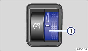 Fig. 87 To the left of the steering wheel: Thumbwheel to adjust instrument panel lighting ①.Read and follow the introductory information and safety information first⇒Introduction to the subject
You can adjust the brightness of the instrument cluster and switch lighting when the lights are on by turning the thumbwheel ⇒ Fig. 87① . On appropriately equipped vehicles, you can adjust other interior lights by pressing the button followed by the
and Lights function keys in the Infotainment system ⇒ Menu and system settings .
In some vehicles with daytime running lights (DRL), the instrument cluster lighting switches off automatically when it is dark outside or when driving through tunnels, for example. You will need to switch the headlights on manually when this happens, so that the vehicle's taillights will turn on ⇒ Lights and vision – features .
For vehicles equipped with halogen headlights: The headlight range cannot be manually adjusted. If you believe the headlights are not properly adjusted or are not sure, have them checked immediately by an authorized Volkswagen dealer or an authorized Volkswagen Service Facility ⇒ .
For vehicles equipped with HID (Xenon) headlights: The headlights are equipped with an automatic leveling feature that automatically adjusts the headlight range to the vehicle loading condition once the low beams are switched on ⇒ .
WarningHeadlights that are aimed too high because of the way the vehicle is loaded can blind and distract other drivers. This can lead to a crash and serious personal injuries.
WarningIf the automatic leveling feature of the headlights does not work properly or at all, the headlights could blind and distract other drivers. This can lead to a crash and serious personal injuries.
Read and follow the introductory information and safety information first⇒Introduction to the subject
| Button | Function |
|---|---|
|
|
Door contact button. Press the button, and the interior lights come on automatically when the vehicle is unlocked, a door is opened, or the vehicle key is removed from the ignition. The lights go out about 20 seconds after you close the doors. They also go out when you lock the vehicle or switch on the ignition. Press the button back out again to switch the door contact feature off. |
|
|
Reading light on or off. |
|
|
Rear interior lights on. |
The glove and luggage compartments may have lights that come on automatically when they are opened and go off when they are closed.
When the ignition and the headlights are switched on, ambient lights in the doors and footwells light up.
On appropriately equipped vehicles, you can adjust the brightness of the ambient lighting in the Infotainment system by pressing the button followed by the
and Lights function keys ⇒ Menu and system settings .
The interior and reading lights go out when you lock the vehicle or a few minutes after you remove the vehicle key from the ignition. This helps to prevent unnecessary drain on the vehicle battery.
Introduction to the subjectIn this chapter you will find information on the following subjects:⇒ Sun visors ⇒ Windshield made of heat-insulating glass WarningSun visors can reduce visibility.
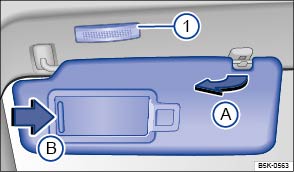 Fig. 88 In the headliner: Sun visor.Read and follow the introductory information and safety information first⇒Introduction to the subject
On some vehicles, you can slide the sun visor towards the rear of the vehicle after swiveling it over to the door.
A vanity mirror is behind a cover in the sun visor. Your vehicle may also be equipped with a light ⇒ Fig. 88① that comes on when you slide the cover Ⓑ open.
The light goes out when you shut the cover or if you flip the sun visor up again.
The interior light above the sun visor goes out after several minutes. This helps to prevent unnecessary drain on the vehicle battery.
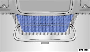 Fig. 89 Heat-reflective windshield with communications window (blue shaded area).Read and follow the introductory information and safety information first⇒Introduction to the subject
Windshields made of insulating glass have a transparent metallic infrared-reflecting coating. There is an uncoated area (communications window) just above the inside rearview mirror ⇒ Fig. 89 . This serves as a communications window for transmitting signals to and from electronic components and accessories.
The uncoated area must not be blocked on the inside or outside or covered with stickers because this can cause the electronic components to malfunction.
Introduction to the subjectIn this chapter you will find information on the following subjects:⇒ Indicator light ⇒ Windshield wiper lever ⇒ Windshield wiper functions ⇒ Windshield wiper service position ⇒ Rain sensor ⇒ Checking and refilling windshield washer fluid WarningWindshield washer fluid without enough frost protection can freeze on the windshield and reduce visibility.
WarningWorn or dirty wiper blades reduce visibility and increase the risk of accidents and severe injuries.
NoteTo help prevent damage to the wiper blades and the wiper motor when it is cold outside, always make sure that blades are not frozen to the windshield before operating the wipers. Using the windshield wiper service position can be helpful in cold weather so the wipers do not freeze to the windshield ⇒ Windshield wiper service position .
Read and follow the introductory information and safety information first⇒Introduction to the subject
Your vehicle may be equipped with an indicator light that comes on when the windshield washer fluid level is low.
| Lights up | Proper response |
|---|---|
|
|
Not enough windshield washer fluid. Refill windshield washer reservoir at the next opportunity ⇒ Checking and refilling windshield washer fluid . |
When the ignition is switched on, several warning and indicator lights come on briefly for a function check. They go out after a few seconds.
NoteFailure to heed warning lights or text WARNINGS can result in vehicle damage.
Displayed in color on an instrument cluster with color display.
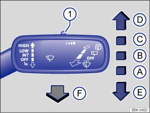 Fig. 90 Operating the front windshield wipers.
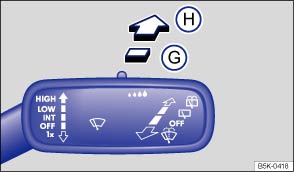 Fig. 91 Operating the rear wiper.Read and follow the introductory information and safety information first⇒Introduction to the subject
|
Move the lever to the desired position ⇒ :
|
||
|---|---|---|
| Ⓐ |
|
Wiper switched off. |
| Ⓑ |
|
Intermittent wiping for the front windshield. Rain sensor active (if equipped). |
| Ⓒ |
|
Slow wiper speed. |
| Ⓓ |
|
Fast wiper speed. |
| Ⓔ |
|
One-tap wiping – brief wiping. Hold the lever pressed down longer to wipe more often. |
| Ⓕ |
|
Pull the lever toward the steering wheel to activate the front windshield washers, then release. |
| Ⓖ |
|
Intermittent wiping for the rear window. The wiper wipes about every 6 seconds. |
| Ⓗ |
|
Press the lever forward as far as it will go to activate the rear window washers, then release to stay in intermittent wiping mode (position Ⓖ). Pull the lever toward the steering wheel to turn the rear wiper off. |
| ① |
|
Switch for adjusting the windshield wiper interval settings (vehicles without a rain sensor) or the sensitivity of the rain sensor (vehicles with a rain sensor). |
NoteTo help prevent damage to the wiper blades and the wiper motor when it is cold outside, always make sure that blades are not frozen to the windshield before operating the wipers. Using the service position can be helpful in cold weather so the wipers do not freeze to the windshield ⇒ Windshield wiper service position .
NoteNever switch on the windshield wipers when the windshield is dry because the windshield can be scratched.On some vehicles, the windshield wipers work only if the ignition is switched on and the engine hood is closed. The windshield wipers turn off automatically when the engine hood is opened. The rear window wiper turns off when the trunk lid is opened.The intermittent wiping for the front windshield depends on the driving speed. The higher the speed, the faster the wipers move.If the front wipers are on, the rear wiper is switched on automatically when backing up.
If the wiper blades freeze to the windshield, loosen them carefully. Volkswagen recommends using a deicing spray.
Read and follow the introductory information and safety information first⇒Introduction to the subject
| Wiper performance in different situations: | |
|---|---|
| When the vehicle is not moving: | The wiper speed changes temporarily to the next lower speed. |
| During automatic wipe/wash: | While the washer system is working, the Climatronic (if equipped) switches to recirculation for about 30 seconds to help prevent the washer fluid odor from entering the vehicle interior. |
| During intermittent wiping: | Speed-dependent interval control: The higher the vehicle speed, the faster the wipers move. |
Some vehicles are equipped with heated washer nozzles. The heating thaws frozen washer nozzles, but not the fluid supply hoses. When the ignition is switched on, the heat applied to the washer nozzles is automatically regulated depending on the outside air temperature.
The headlight washer system cleans the headlight glass.
If the ignition and the headlights (high or low beams) are switched on, the headlights are cleaned the first time and every fifth time the front windshield washers are activated. This happens only when the low or high beams are on when the windshield wiper lever is pulled towards the steering wheel. However, the headlights must still be washed by hand periodically (for instance, during refueling) to get rid of hard-to-remove dirt (like insect splatter).
To help make sure that the headlight washer system works during winter weather, always keep the headlight washer nozzles free of snow and remove any ice with a deicer spray before driving. Use a deicer spray to remove any ice.
If there is something on the windshield, the wiper will try to wipe it away. If it continues to block the wiper, the wiper will stop moving. Remove the obstacle and switch the wiper on again.
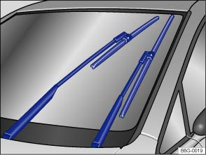 Fig. 92 Windshield wiper in service position.Read and follow the introductory information and safety information first⇒Introduction to the subject
In the service position, the wiper arms can be lifted away from the windshield ⇒ Fig. 92 . The wipers are moved to the service position as follows:
.Carefully fold the wiper arms back onto the windshield before driving! Switch the ignition on and press the windshield wiper lever down briefly ⇒ Fig. 90Ⓔ . The wiper arms move back to their original position.
Note
The windshield wiper arms can be moved to the service position only when the vehicle is not moving.
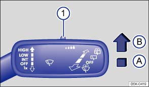 Fig. 93 Windshield wiper lever: Adjusting the rain sensor ① (if equipped).
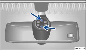 Fig. 94 Inside the front windshield above the inside mirror: Sensitive rain sensor surface.Read and follow the introductory information and safety information first⇒Introduction to the subject
When switched on, the rain sensor automatically shortens or lengthens the time between wiping intervals depending on how hard it is raining ⇒ . The rain sensor's sensitivity can be adjusted manually ⇒ Fig. 93① .
On appropriately equipped vehicles, the automatic wipe function of the rain sensor can be turned on and off in the Infotainment system by pressing the button followed by the
and Mirrors and wipers function keys ⇒ Menu and system settings .
Push the lever into the desired position ⇒ Fig. 93 :
Rain sensor off (windshield wiper lever home position).Rain sensor active – automatic wiping as needed.Adjust the sensitivity of the rain sensor:
After switching the ignition off and back on again, the rain sensor stays on and works again when the wiper lever is in position Ⓑ.
The rain sensor may misread what is happening in the detection zone of its sensitive rain-sensor surface⇒ Fig. 94 (arrows) and not work for a number of reasons, which may include:
WarningThe rain sensor cannot always recognize rain and activate the wipers.
Clean the rain sensor's sensitive surface ⇒ Fig. 94 (arrows) regularly and check the wiper blades for wear or damage.To remove wax and coats of polish safely, we recommend using an alcohol-based windshield cleaner.
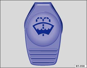 Fig. 95 In the engine compartment: Cap of the windshield washer fluid reservoir.Read and follow the introductory information and safety information first⇒Introduction to the subject
Check the windshield washer fluid level regularly and refill as necessary.
There is a filter screen in the filler neck of the windshield washer fluid reservoir. The screen helps to keep large particles and debris from getting into and clogging the windshield washer nozzles when adding windshield washer fluid. Take the screen out only to clean it. If the screen is damaged or missing, have it replaced immediately, otherwise the system may become clogged and not work properly.
. Follow the directions on the container. .Depending on vehicle equipment, the windshield washer fluid reservoir holds between 3.1–5.2 quarts (3–5 liters).
WarningNever mix antifreeze or similar additives into the windshield washer reservoir. This could produce an oily film on the windshield, which would considerably reduce visibility.
Note
Introduction to the subjectIn this chapter you will find information on the following subjects:⇒ Inside mirror ⇒ Outside mirrors
For your driving safety, it is important that you properly adjust the outside mirrors and the inside mirror before you start driving ⇒ .
The outside mirrors and the inside mirror help you see and adapt your driving to traffic behind you. Remember that the inside and outside rearview mirrors will not show everything behind you. There can be blind spots. Blind spots can be significantly larger if the mirrors are not properly adjusted.
WarningAdjusting mirrors when the vehicle is moving can cause driver distraction, accidents, and serious personal injury.
WarningSelf-dimming rearview mirrors contain an electrolyte fluid which can leak if the mirror glass is broken. Electrolyte fluid can irritate the skin, eyes, and respiratory system.
NoteBroken glass in the self-dimming rearview mirrors can cause electrolyte fluid leakage. Liquid electrolyte leaked from a broken mirror glass will damage any plastic surfaces it comes in contact with. Clean up spilled electrolyte fluid immediately with clear water and a sponge.
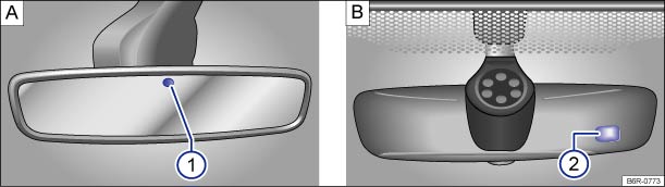 Fig. 96 Self-dimming rearview mirror (if equipped).
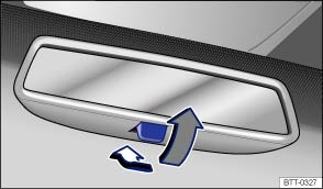 Fig. 97 Manually adjustable inside mirror.Read and follow the introductory information and safety information first⇒Introduction to the subject
Adjust the inside mirror to make sure that there is good visibility through the rear window.
For example, visibility through the rear window could be impaired if there is a sunshade on the rear window or clothing on the luggage compartment cover, or if the rear window is covered with ice, snow, or dirt.
There are two sensors in the interior mirror housing:
If the ignition is switched on, the mirror automatically darkens depending on the amount of light shining into the vehicle from the rear.
The self-dimming feature is deactivated when you shift the transmission into reverse or switch on the interior lights or the reading light.
Do not attach external navigation devices to the windshield or in the vicinity of the self-dimming inside mirror ⇒ .
WarningThe illuminated display on an external navigation device can cause the self-dimming inside mirror to malfunction, which can result in crashes and serious injuries.
If the light striking the sensor is filtered or blocked (such as by a sunshade), the self-dimming inside mirror will not work properly or may not work at all.
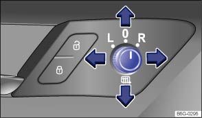 Fig. 98 In the driver door: Adjusting knob for the outside mirrors.Read and follow the introductory information and safety information first⇒Introduction to the subject
When the ignition is switched on, turn the knob in the driver door ⇒ Fig. 98 to adjust the outside mirrors.
| Turn the knob to the desired position: | |
|---|---|
|
|
Switch on outside mirror heating. Heats only at outside air temperatures below +68 °F (+20 °C). |
|
|
Adjust the left outside mirror by pressing the knob to left/right and up/down. |
|
|
Adjust the right outside mirror by pressing the knob to left/right and up/down. |
|
|
Neutral position. No heating or adjustment possible. |
WarningImproper use of the folding outside mirrors can cause personal injury.
WarningIncorrectly estimating distances with the right outside mirror can cause collisions and serious injury.
NoteAlways fold in the outside mirrors when taking the vehicle through an automatic car wash.To reduce fuel consumption, use outside mirror heating only when needed.When first switched on, outside mirror heating works with maximum heat for about 2 minutes.If power mirror adjustment does not work, the outside mirrors can be adjusted by hand by pressing on the edges of the mirror surface.
Introduction to the subjectIn this chapter you will find information on the following subjects:⇒ Stowing luggage ⇒ Driving with an open trunk lid ⇒ Driving a loaded vehicle ⇒ Weights and axle weights
Always stow heavy objects in the luggage compartment and make sure that the rear seat backrests are securely latched. Always use the tie-downs in the luggage compartment and secure the objects with suitable straps. Never overload the vehicle. Remember that the vehicle load, as well as how it is distributed, can affect vehicle handling and braking ⇒ .
WarningUnsecured or incorrectly stowed items can fly through the vehicle, causing serious personal injury during hard braking or sharp steering or in an accident. Loose items can also be struck and thrown through the passenger compartment by the front airbags if they inflate. To help reduce the risk of serious personal injury:
WarningHeavy loads will influence the way your vehicle handles and increase stopping distances. Heavy loads that are not properly stowed or secured can cause loss of control and serious injury.
Read and follow the introductory information and safety information first⇒Introduction to the subject
NoteWires in the rear windows such as for heating or for an antenna can be damaged by objects that rub against them.If applicable, please review the information on loading a trailer ⇒ Trailer towing and a roof rack ⇒ Roof rack .
Read and follow the introductory information and safety information first⇒Introduction to the subject
Driving with an open trunk lid can lead to serious personal injury. If you have to drive with an open trunk lid, make sure that all objects and the lid itself are properly secured and take appropriate measures to keep toxic exhaust fumes from entering the vehicle.
WarningDriving with an unlatched or open trunk lid can lead to serious personal injury.
WarningDriving with an open trunk lid can cause poisonous carbon monoxide in the engine exhaust to get into the passenger compartment.
NoteThe open trunk lid changes the vehicle height.
Read and follow the introductory information and safety information first⇒Introduction to the subject
For good handling when driving a loaded vehicle, please observe the following:
WarningHeavy loads can change the way your vehicle handles and increase stopping distances. Heavy loads that are not properly stowed or secured can shift suddenly, causing loss of control and serious injury.
Read and follow the introductory information and safety information first⇒Introduction to the subject
The actual gross weight of any vehicle depends on the engine, basic equipment, any factory-installed optional equipment for the given model, and any accessories that have been installed. The Gross Vehicle Weight Rating (GVWR) and the Gross front and Rear Axle Weight Ratings (GAWR) for a given vehicle are printed on the vehicle's Safety Compliance Certification Label on the driver door jamb.
The Gross Vehicle Weight Rating includes the weight of the vehicle itself with all of its factory-installed equipment, plus a full tank of gasoline, the engine oil and coolant, all vehicle occupants (150 lbs/68 kg per seating position) and cargo.
The Gross Axle Weight Ratings specify the maximum allowable load for each axle.
The cargo payload may not be increased by using a roof rack without commensurately reducing the weight from vehicle occupants ⇒ .
Vehicle payload consists of the combined weight of the following:
Please refer to the Gross Vehicle Weight Rating (GVWR) and the Gross front and rear Axle Weight Ratings (GAWR) for your vehicle, which are printed on the vehicle's Safety Compliance Certification Label on the driver door jamb ⇒ Important vehicle labels .
WarningExceeding maximum permissible weight ratings can result in vehicle damage, accidents, and serious personal injury.
Note
Introduction to the subjectIn this chapter you will find information on the following subjects:⇒ Folding the rear seat backrest forward and back into place ⇒ Luggage compartment cover ⇒ Luggage compartment pass-through ⇒ Tie-downs ⇒ Shopping bag hooks ⇒ Variable luggage compartment floor
Always stow heavy objects in the luggage compartment and make sure that the rear seat backrests are securely latched in their upright position. Always secure objects to the tie-downs with suitable straps. Never overload the vehicle. Remember that the vehicle load, as well as how it is distributed, can affect vehicle handling and braking ⇒ .
WarningAn open or unlocked luggage compartment poses special risks for children.
WarningUnsecured or incorrectly stowed items can fly through the vehicle, causing serious personal injury during hard braking or sharp steering or in an accident. Loose items can also be struck and thrown through the passenger compartment by the front airbags if they inflate. To help reduce the risk of serious personal injury:
WarningTransporting heavy objects causes the handling characteristics of the vehicle to change and increases braking distances. Heavy loads which are not properly stowed or secured in the vehicle can lead to a loss of vehicle control and cause serious personal injury.
NoteThe defroster heating wires or antenna in the rear window can be damaged by objects that rub against them.The ventilation slots in the luggage compartment must not be blocked so that stale air can escape from the vehicle.
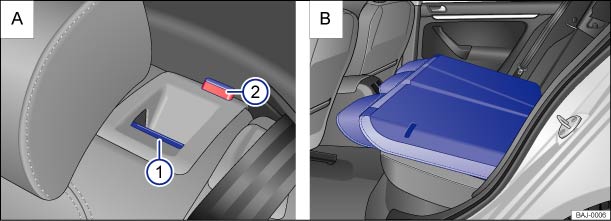 Fig. 99 : Rear seat bench: Release button ① and red mark on the indicator ②. : Seat backrest folded forward.Read and follow the introductory information and safety information first⇒Introduction to the subject
The rear seat backrest is divided into 2 sections. Each section of the rear seat backrest can be folded down individually to increase luggage space.
If the rear seat backrest is folded down, no one, including children, may ride on the rear seat.
.WarningImproper folding and improper latching of the rear seat backrest can cause serious personal injury.
NoteBefore folding the rear seat backrest forward, adjust the front seats so that the rear seat's head restraint or backrest cushion will not touch the front seats.
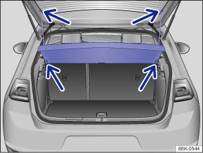 Fig. 100 In the luggage compartment: Installing and removing the luggage compartment cover.Read and follow the introductory information and safety information first⇒Introduction to the subject
When you open or close the trunk lid, the supporting cords, when attached, will automatically raise or lower the luggage compartment cover.
You can put light articles of clothing on the luggage compartment cover. But remember that your view through the rear window must not be obstructed.
WarningIn a sudden braking or other maneuver, or in a collision, unsecured or improperly secured objects or animals on the luggage compartment cover can cause serious personal injury.
WarningClothes or other items on the luggage compartment cover behind the rear seat backrest may limit visibility and cause accidents and severe personal injuries.
NoteTo help prevent damage to the luggage compartment cover, the luggage compartment may only be loaded to a height at which the luggage compartment cover will not press on the cargo when the trunk lid is closed.NoteThings on the luggage compartment cover can damage it.
The ventilation slots in the luggage compartment must not be blocked so that stale air can escape from the vehicle.
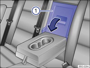 Fig. 101 In the rear seat backrest: Opening the luggage compartment pass-through.
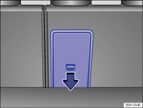 Fig. 102 In the luggage compartment: Opening the pass-through.Read and follow the introductory information and safety information first⇒Introduction to the subject
There may be a pass-through for transporting things like skis in the rear seat backrest behind the center armrest.
To help prevent soiling the vehicle interior, cover dirty items before sliding them into the pass-through.
If the center armrest is folded down, no one can sit on the middle seat of the rear bench.
The pass-through can also be opened from the luggage compartment. Press the release lever ⇒ Fig. 102 in the direction of the arrow and push the cover forward.
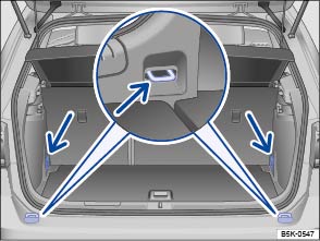 Fig. 103 In the luggage compartment: Tie-downs.Read and follow the introductory information and safety information first⇒Introduction to the subject
There are tie-downs in the front and rear of the luggage compartment, which you can use to secure luggage or other items ⇒ Fig. 103 (arrows).
Some tie-downs may have to be folded open for use.
Elastic straps can snap back toward you if they are not properly attached ⇒ .
If you use elastic straps to secure items in the luggage compartment, be sure to securely attach them to the tie-downs just behind the rear seat backrest first and then to the tie-downs at the loading edge of the luggage compartment.
Remove the hooks from the tie-downs in the reverse order described above, first from the tie-downs at the loading edge and then from the tie-downs behind the rear seat backrest so that if the hooks come loose suddenly, they will move away from you.
WarningUnsuitable, worn, or damaged tie-down straps (elastic or non-elastic) can snap or come loose during braking or other maneuvers or in a collision. Objects secured with these straps can then come loose and fly through the passenger compartment, causing severe personal injuries or death.
WarningElastic straps have to be stretched when being attached to the tie-downs in the luggage compartment. Hooks on these straps can cause serious personal injury if not handled properly and attached securely.
The maximum load for the tie-downs is about 380 lbs. (172 kg).For suitable straps and luggage stowage systems, please see an authorized Volkswagen dealer or authorized Volkswagen Service Facility.
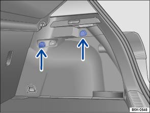 Fig. 104 In the luggage compartment: Shopping bag hooks.Read and follow the introductory information and safety information first⇒Introduction to the subject
Shopping bag hooks may be located in the upper left and right areas of the luggage compartment ⇒ Fig. 104 (arrows).
WarningNever use the shopping bag hooks as tie-downs. The hooks could break off during sudden braking maneuvers or in a collision.NoteThe maximum load for each shopping bag hook is 5 lbs. (2.5 kg).
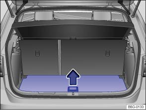 Fig. 105 In the luggage compartment: Opening the variable luggage compartment floor.
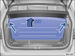 Fig. 106 In the luggage compartment: Variable luggage compartment floor folded up.Read and follow the introductory information and safety information first⇒Introduction to the subject
Some models are equipped with a variable luggage compartment floor, which is height-adjustable.
.WarningDuring hard braking or an accident, loose objects can fly through the passenger compartment and cause serious or even fatal injuries.
NoteDo not let the luggage compartment floor fall freely when closing it. Always guide it down into place. The trim or the luggage compartment floor could be damaged.If you store the luggage compartment cover under the variable luggage compartment floor, insert the luggage compartment floor into the upper guides.
Introduction to the subjectIn this chapter you will find information on the following subjects:⇒ Attaching the roof rack base carrier and roof rack ⇒ Securing a load on the roof rack
The roof of your vehicle has been designed to optimize aerodynamics and does not have traditional rain gutters that are used to attach many kinds of roof racks.
Since the rain gutters are molded into the roof to provide efficient aerodynamics, only Volkswagen-approved base carrier mounts and roof racks can be used.
WarningTransporting heavy or bulky loads on the roof rack will change the way the vehicle handles by shifting the vehicle's center of gravity and increasing the wind drag.
Note
If a roof rack is installed, fuel consumption increases due to increased air resistance.
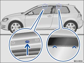 Fig. 107 Mounting points for the base carrier and roof rack on 2-door vehicles.
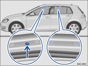 Fig. 108 Mounting points for the base carrier and roof rack on 4-door vehicles.Read and follow the introductory information and safety information first⇒Introduction to the subject
The base carrier is the basis of a complete roof rack system. For safety reasons, additional attachments are necessary for transporting luggage, bicycles, surfboards, skis, and small boats. Suitable accessories can be purchased from your authorized Volkswagen dealer or authorized Volkswagen Service Facility.
Always attach the base carrier and roof rack correctly.
Always carefully follow the installation instructions from the base carrier or roof rack manufacturer.
The front mounting holes are on the underside of the roof frame. They are sealed with plastic screws that must be removed before installation ⇒ Fig. 107 (magnified view on left). The holes are only visible when the door is open. The rear markings for the base carrier are above the rear side windows ⇒ Fig. 107 (magnified view on right).
Only mount the roof rack base carrier on the markings shown in the illustration.
Once you have installed the base carrier correctly, you can secure the roof rack on the base carrier according to the manufacturer's instructions.
Always attach the base carrier and roof rack correctly.
Always carefully follow the installation instructions from the base carrier or roof rack manufacturer.
The front mounting holes are on the underside of the roof frame. They are sealed with plastic screws that must be removed before installation ⇒ Fig. 108 (magnified view on left). The rear markings for the base carrier are on the underside of the roof frame ⇒ Fig. 108 (magnified view on right).
The holes and markings are only visible when the door is open.
Only mount the roof rack base carrier on the markings shown in the illustration.
Once you have installed the base carrier correctly, you can secure the roof rack on the base carrier according to the manufacturer's instructions.
WarningInstalling or using a base carrier or roof rack improperly can cause the entire system to fly off the vehicle, causing accidents and injuries.
Follow the installation instructions provided for installing the roof rack system. Always carry them in the vehicle.
Read and follow the introductory information and safety information first⇒Introduction to the subject
It is not possible to secure a load unless the roof rack system has been properly installed ⇒ .
The maximum permissible roof load is 165 lbs. (75 kg). The roof load is the combined weight of the roof rack and the items being carried on the roof ⇒ .
Be sure you know the weight of the roof rack and the items you want to transport on the roof. Weigh them if necessary. Never carry a total of more than the maximum permissible roof load.
When using a roof rack with a lower load limit, do not load the rack to the maximum weight mentioned above. In this case, you may only load the roof rack to the weight limit specified in the system's installation instructions.
Distribute the load evenly and secure it properly ⇒ .
After the base carrier and roof rack have been installed, check all bolts and fasteners after driving a short time and at regular intervals thereafter.
WarningIf the maximum permissible roof load is exceeded, accidents and substantial vehicle damage may occur.
WarningLoose or improperly secured items can fall off the roof rack and cause accidents and injuries.
Introduction to the subjectIn this chapter you will find information on the following subjects:⇒ Technical requirements ⇒ Hitching up and connecting a trailer ⇒ Loading the trailer ⇒ Driving with a trailer ⇒ Ball mount ⇒ Retrofitting a trailer hitch ⇒ Maximum permissible trailer weight
Obey country-specific requirements about trailer towing and trailer hitches.
Volkswagen does not recommend installing a trailer hitch on your vehicle. Your Volkswagen was mainly designed for carrying passengers. If you plan to tow a trailer, please remember your vehicle will be performing a job for which it was not primarily intended. The additional load will affect durability, handling, fuel economy, and performance, and may require the vehicle to be serviced more often.
Trailer towing not only places more stress on the vehicle, it calls for more concentration from the driver. Always follow the operating and driving instructions given, and use common sense.
Under winter conditions, install winter tires on the vehicle and the trailer.
For technical reasons, the vehicle body structure is not designed for the installation of a trailer hitch.
Never install a trailer hitch on Golf R models. Installing a trailer hitch will do considerable damage to the vehicle ⇒ .
WarningRiding in a trailer is dangerous and may be illegal.WarningImproper use of the trailer hitch can cause accidents and injuries. An improperly installed, incorrect, or damaged trailer hitch can cause the trailer to separate from the towing vehicle and cause serious personal injuries.
WarningImproper trailer towing can cause loss of vehicle control and serious personal injury.
WarningInstalling a trailer hitch on Golf R models can cause an accident and serious personal injuries.
NoteInstalling a trailer hitch of any kind on Golf R models will cause expensive damage to your vehicle that will not be covered by any Volkswagen Limited Warranty.If you are driving a new vehicle or a vehicle with a new or rebuilt engine, do not tow a trailer during the break-in period, about 600 miles (1000 km) ⇒ Parts, accessories, repairs, and modifications .If you tow a trailer, your vehicle may need maintenance more often because of the extra load it has to move.When you are not towing, remove the trailer hitch ball. This helps keep the trailer hitch from causing damage to your vehicle and to others if your vehicle is hit from behind.Some models need a trailer hitch to tow or tow-start other vehicles. You may want to always carry the ball mount in the vehicle after it has been removed. Be sure to stow it securely.
Read and follow the introductory information and safety information first⇒Introduction to the subject
Use only a weight-carrying trailer hitch designed and approved for the gross weight of the trailer you want to tow. The trailer hitch must be suitable for your vehicle and trailer and must be securely bolted to the appropriate place on the vehicle chassis. Use only a trailer hitch with a removable ball mount. Always check with the trailer hitch manufacturer to make sure that you are using the correct trailer hitch and carefully follow the hitch manufacturer's instructions. Never install a weight-distributing or load-equalizing trailer hitch on your vehicle. The vehicle is not designed for this kind of trailer hitch ⇒ .
Never install a trailer hitch on the bumper or on the bumper attachments. The trailer hitch must not interfere with the impact-absorbing bumper system. Do not make any changes to the vehicle exhaust and brake systems. From time to time, check that all trailer hitch mounting bolts are securely fastened. When you are not towing, remove the trailer hitch. This helps keep the trailer hitch from causing damage if your vehicle is hit from behind.
Towing a trailer makes the engine and its cooling system work harder. It is important that the engine cooling system is up to the job. Make sure that the cooling system has enough coolant.
If your trailer has its own brakes, make sure it meets all regulations. The trailer brake system must never be directly connected to the vehicle's brake system.
Always use safety chains between your vehicle and the trailer ⇒ Hitching up and connecting a trailer .
Trailer lights must meet all regulations ⇒ Hitching up and connecting a trailer .
Never connect the trailer lights directly to the electrical system of your vehicle.
If you cannot see the traffic behind you using the regular outside mirrors, then you must install extended mirrors. Extended mirrors may also be required by law in some countries/states/provinces. Always adjust the outside mirrors before driving. It's vital that you always have a clear view to the rear of the vehicle.
Do not exceed the power ratings listed in the chart below.
| Electrical load | Maximum power |
|---|---|
| Brake lights total | 108 watts |
| Turn signals per side | 54 watts |
| Side marker lights total | 100 watts |
| Taillights total | 54 watts |
Warning
Note
If you tow a trailer frequently, Volkswagen recommends having the vehicle serviced between the regular maintenance and inspection intervals because of the extra load it has to pull.
Read and follow the introductory information and safety information first⇒Introduction to the subject
Always make sure that the safety chains are properly attached to the towing vehicle. Leave enough slack in the chains so that you can go around corners without stretching the chains. The safety chains must not drag on the ground, however.
Make sure that the trailer lights work properly and meet legal requirements. Do not exceed the maximum power consumption for the trailer ⇒ Technical requirements .
WarningImproper connections to the vehicle electrical system can cause malfunctions that affect the entire vehicle electrical system, which can lead to accidents and serious personal injury.
NoteNever attach a trailer to the vehicle or leave it attached to the vehicle when the trailer is supported by a trailer jack or blocks. Various things (such as a change in trailer or vehicle load or a flat tire) can lower or raise the vehicle. This subjects the trailer hitch and the trailer to strong forces that can damage the vehicle or the trailer.If the engine is switched off and accessories in the trailer are on and use electricity from the vehicle, the vehicle battery will be drained as long as the electrical systems of the vehicle and the trailer are connected.
Read and follow the introductory information and safety information first⇒Introduction to the subject
Maximum permissible trailer weight is the load that the vehicle can tow ⇒ . The tongue load or tongue weight is the load pressing down on the trailer hitch ball mount.
The maximum permissible trailer weight and tongue weight for your vehicle are listed on ⇒ Maximum permissible trailer weight in this Manual.
The trailer load and tongue weight on the type identification plate for the trailer hitch are only test values. The vehicle-specific figures are often lower than these values. In some countries, but generally not in the United States, the vehicle-specific figures are listed in the official vehicle documents. Specifications in official vehicle documents always take precedence.
To help ensure optimum handling and driving safety, Volkswagen recommends always using the maximum permissible tongue weight. If the tongue weight is too low, the vehicle and trailer will not handle as well.
Tongue weight increases the load on the rear axle and, in turn, reduces the remaining load your vehicle can carry ⇒ Determining the correct load limit .
Combined towing weight is the weight of the loaded towing vehicle plus the weight of the loaded trailer.
This vehicle has not been designed to tow a Class II trailer and must never be retrofitted to tow a Class II trailer. Always make sure that your vehicle has been designed to tow the trailer you want to use and that it is legal to tow the trailer where you will be driving.
The weight distribution in the vehicle and trailer must be balanced. Use the maximum permissible tongue weight and make sure that the load in the trailer is evenly distributed and that it is not front-heavy or tail-heavy:
Always follow the trailer manufacturer's tire pressure recommendations for the trailer tires.
When towing, inflate the towing vehicle's tires to the maximum permissible pressure listed on the tire pressure label ⇒ Tire inflation pressure .
WarningExceeding the gross weight ratings for axle, tongue, vehicle, trailer or combined weight can cause accidents and serious personal injury.
WarningTrailer loads that are not properly secured can shift when the vehicle is moving or braking and suddenly change the way the vehicle handles, causing accidents and severe injuries.
Read and follow the introductory information and safety information first⇒Introduction to the subject
Towing a trailer can raise the front end of the vehicle enough for the low beams to blind other road users. If your vehicle does not have headlight range adjustment, have the headlights adjusted by an authorized Volkswagen dealer or authorized Volkswagen Service Facility. Vehicles with Xenon headlights self-adjust to vehicle load and do not need manual adjustment.
Depending on how steep the hill is and the combined towing weight, a parked vehicle with trailer can roll backwards when you first start moving.
When starting off with a trailer on a hill:
WarningImproper trailer towing can cause loss of vehicle control and serious personal injury.
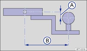 Fig. 109 Dimensions of the ball mount support.Read and follow the introductory information and safety information first⇒Introduction to the subject
Your vehicle is not equipped with a trailer hitch or preparations for the installation of a trailer hitch. If you must tow a trailer, you must have the necessary electrical wiring and socket together with a suitable trailer hitch installed. Because towing a trailer places a great deal of stress on the vehicle, the attachment of a trailer to the vehicle and the dimensions of the receiver and ball mount are very important so that the extra forces the vehicle has to withstand can be properly handled.
The receiver used requires both a ball mount and a ball that meet special requirements regarding geometry and size. This applies to both the height of the ball above the surface where it attaches ⇒ Fig. 109Ⓐ , and the pin-to-ball distance ⇒ Fig. 109Ⓑ .
These dimensions are important because they help determine the way that the forces that arise during towing are applied to the receiver and its attachments to the vehicle. If you buy a ball mount and ball, make sure that they meet the following specifications.
A ball mount and ball combination that does not meet these specifications can damage your vehicle and may even fail in use ⇒ .
Never install a weight distributing or load equalizing trailer hitch on your vehicle. The vehicle is not designed for this kind of trailer hitch ⇒ .
WarningAn improperly installed or unsuitable trailer hitch can cause the trailer to separate from the towing vehicle and result in a major accident with serious personal injuries.
CautionThe ball mount sticks out behind the rear bumper and can cause injury to pedestrians and cyclists.
Note
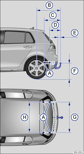 Fig. 110 Dimensions and attachment points for retrofitting a trailer hitch.Read and follow the introductory information and safety information first⇒Introduction to the subject
Volkswagen recommends having the trailer hitch retrofit performed by a qualified workshop because cooling system modifications or the installation of heat shields may be necessary. Volkswagen recommends that you see an authorized Volkswagen dealer or an authorized Volkswagen Service Facility before having a trailer hitch installed on your vehicle.
When retrofitting a trailer hitch, the specified distance dimensions must be strictly adhered to. Under no circumstances may the distance from the center of the hitch ball to the surface of the road ⇒ Fig. 110Ⓕ be less than the specified minimum. This minimum height must be present even when the vehicle is fully loaded and subject to the maximum tongue weight.
Distance dimensions⇒ Fig. 110 :
Attachment points.33 inches (838 mm)20.2 inches (513 mm)11.5 inches (293 mm) at least 2.6 inches (65 mm)
 13.8 – 16.5 inches (350 – 420 mm)
 41.1 inches (1043 mm)
 41.3 inches (1048 mm)
WarningImproper or incorrect connections to the vehicle electrical system can cause malfunctions that affect the entire vehicle electrical system and cause accidents and serious personal injury.
WarningAn improperly installed or unsuitable trailer hitch can cause the trailer to separate from the towing vehicle and result in a major accident with serious personal injuries.
Read and follow the introductory information and safety information first⇒Introduction to the subject
| Model | Maximum power output | Engine code | Transmission | Trailer with brake | Trailer without brake | Tongue weight |
|---|---|---|---|---|---|---|
| Golf |
1.8 L/170 hp (125 kW) gasoline engine |
CXBA, CXBB 1.8L |
6S manual | |||
| 6S automatic | ||||||
| Golf GTI |
210 hp (155 kW) gasoline engine |
CNTA, CXCA 2.0L |
6S manual | |||
| DSG | ||||||
|
220 hp (162 kW) gasoline engine |
CXCB 2.0T |
6S manual | ||||
| DSG | ||||||
| Golf R |
292 hp (215 kW) gasoline engine |
CYFB 2.0T |
6S manual | This vehicle cannot be used to tow a trailer⇒ . | ||
| DSG | ||||||
The Gross Vehicle Weight Rating and the Gross Axle Weight Rating must not be exceeded, even with a trailer. These ratings are listed on the safety compliance label on the driver front door jamb ⇒ Important vehicle labels . When a trailer is towed, the weight of the ball mount and the tongue weight of the trailer are added to the vehicle weight ⇒ Determining the correct load limit .
The trailer weight ratings given above are valid only up to altitudes of 3000 ft (1000 m) above sea level. The maximum permissible combined towing weight must be reduced by about 10% for every 3000 ft (1000 m), or portion thereof, of additional altitude.
WarningExceeding the gross trailer weight rating and tongue weight can cause accidents and serious personal injury.
NoteExceeding the gross weight ratings can cause extensive vehicle damage that is not covered by any Volkswagen Limited Warranty.
Information not available at time of printing.
Introduction to the subjectIn this chapter you will find information on the following subjects:⇒ Tire and wheel handling ⇒ Wheel rims ⇒ New and replacement tires ⇒ Tire inflation pressure ⇒ Tire inflation pressure in cold tires ⇒ Tread depth and tread wear indicators ⇒ Tire wear and damage ⇒ Spare wheel or compact spare wheel ⇒ Tire labeling ⇒ Winter tires ⇒ Snow chains ⇒ Glossary of tire and loading terminology ⇒ Tires and vehicle load limits ⇒ Determining the correct load limit ⇒ UTQG classification
Volkswagen recommends that all work on tires and wheels be done by an authorized Volkswagen dealer or authorized Volkswagen Service Facility. They are familiar with the technical requirements and recommended procedures, have the necessary special tools and spare parts, and can properly dispose of old tires.
WarningNew tires or tires that are old, worn or damaged cannot provide maximum control and braking performance.
For technical reasons it is usually not possible to use wheel rims from other vehicles. Even wheel rims from the same model may not fit properly. Check with an authorized Volkswagen dealer or authorized Volkswagen Service Facility if necessary.
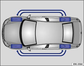 Fig. 111 Tire rotation diagram.Read and follow the introductory information and safety information first⇒Introduction to the subject
Tires may be the least appreciated and most abused parts of a motor vehicle. Tires are very important, since their small patches of rubber are the only contact between your vehicle and the road.
Maintaining correct tire pressure, making sure that your vehicle and its tires do not have to carry more weight than they can safely handle, and regularly inspecting tires for damage (such as cuts, slashes, irregular wear, and overall condition) are the most important things that you can do to help avoid sudden tire failure, including tread separation and blowout.
The tires and wheels are essential parts of the vehicle's design. The tires and wheels approved by Volkswagen are specially matched to the characteristics of the vehicle for good road holding and safe handling when in good condition and properly inflated.
.Unidirectional tires are designed to rotate only in one direction. Unidirectional tires have arrows on the sidewalls that show the direction of rotation ⇒ Tire labeling . Unidirectional tires must always be mounted according to the specified direction of rotation in order to deliver their best grip, braking performance, low road noise, and good wear as well as good hydroplaning resistance.
If you have to mount a tire opposite to its proper direction of rotation, you must drive more carefully, since the tire is no longer being used as designed. This is particularly important on wet roads. You must replace or remount the tire as soon as possible in order to restore the correct direction of rotation.
To help ensure even wear on all tires, regular tire rotation according to the diagram ⇒ Fig. 111 is recommended. In this way all tires can have about the same service life.
Volkswagen recommends that you have your tires rotated by an authorized Volkswagen dealer or authorized Volkswagen Service Facility.
Tires age even if they are not being used. Physical and chemical processes reduce tire strength and performance and cause them to harden and become brittle. Old tires can fail suddenly and without warning.
Volkswagen recommends replacing tires that are 6 years and older. This also applies to tires that look new (including the tire on the compact spare wheel) or that seem to still be usable with tread depth that has not yet reached the legal minimum depth ⇒ .
The age of each tire can be determined with the manufacturing date that is part of the U.S. DOT tire identification number (TIN) ⇒ Tire labeling .
Mark tires before removing them to help make sure that the previous location (left, right, front, rear) and rolling direction can be maintained when remounting them. Store tires in a cool, dry and preferably dark place. Do not store tires mounted on wheels standing up.
Tires not mounted on wheels should be covered to help protect them from dirt and stored vertically (sitting on the tread).
Lower profile tires have a wider tread surface, larger rim diameter, and lower sidewalls than conventional wheel/tire combinations ⇒ . Lower profile tires can improve the vehicle’s handling and precision. They may, however, result in a less comfortable ride, for example, on uneven road surfaces.
WarningAggressive fluids and materials can cause visible and invisible tire damage that can cause tire blowouts.
WarningTires age even if they are not being used and can fail suddenly, especially at high speeds, causing loss of vehicle control, accidents, and severe personal injuries.
NoteTires and rims, especially lower profile tires and their rims, can be severely damaged and even destroyed by driving through potholes or over curbs and other obstacles.Always dispose of old tires in accordance with legal requirements.
Read and follow the introductory information and safety information first⇒Introduction to the subject
The design of the wheel bolts is matched to the factory-installed wheels. If different wheels are installed, wheel bolts with the right length and bolt head shape must be used. This helps to ensure that wheels can be mounted securely and that the brakes will work correctly ⇒ Changing a wheel .
In most cases, you cannot use wheel bolts from a different vehicle. Even wheel rims from the same model may not fit properly.
Tires and wheel rims approved by Volkswagen have been matched precisely to your vehicle model and contribute considerably to good handling and safe vehicle performance.
Wheel bolts must always be installed with the correct tightening torque ⇒ Changing a wheel . The required tightening torque for your vehicle's wheel bolts is 88 ft-lbs (120 Nm). After changing a wheel, the bolt torque must be checked as soon as possible with an accurate torque wrench. See an authorized Volkswagen dealer or an authorized Volkswagen Service Facility.
Wheel rims with bolted rim rings have several parts. The parts are bolted together with special screws in a special process. This helps to ensure that they will work properly, prevent leaks, run true and safely. Damaged wheel rims must be replaced, and you must never take them apart or try to repair them yourself. Have an authorized Volkswagen dealer or an authorized Volkswagen Service Facility repair them for you ⇒ .
Light-alloy wheels may have interchangeable decorative covers attached to the rim with self-locking screws. If you want to replace damaged wheel covers, contact your authorized Volkswagen dealer or authorized Volkswagen Service Facility.
WarningUsing improper or damaged wheel rims can affect driving safety, cause accidents and severe personal injury.
WarningImproper loosening and tightening of the bolts on wheel rims with bolted rim rings can cause accidents and severe personal injury.
Read and follow the introductory information and safety information first⇒Introduction to the subject
. .Tire Pressure Monitoring System (TPMS) considerations: The Tire Pressure Monitoring System (TPMS) must be recalibrated whenever you remove and remount or change any wheel or tire on the vehicle, even if the reinstalled or replacement wheels and tires are identical to those that were removed and even if the tire pressure does not change ⇒ Tire Pressure Monitoring System (TPMS) .
WarningNew tires tend to be slippery and must be broken in.
WarningTires must have the required clearance. Tires that do not have enough clearance can rub against parts of the vehicle body, suspension, and brake system, causing brake system failure, tread delamination, and sudden blowouts.
Note
Always dispose of old tires in accordance with legal requirements.If the replacement wheel is different from the tires that you have mounted on your vehicle — for example, winter tires, wider, low-profile tires, or a compact spare — only use the replacement wheel for a short time and drive cautiously.
Although tire size specifications can be the same, the actual dimensions may differ from those nominal values for different tire makes, or the tire contours may be significantly different.
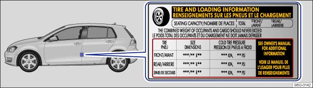 Fig. 112 On the driver door jamb: Location of the tire inflation pressure label.Read and follow the introductory information and safety information first⇒Introduction to the subject
The correct tire inflation pressure for the factory-installed tires is listed on a label. The factory-installed tires may be summer, winter, or all-season tires. The label ⇒ Fig. 112 is on the driver door jamb.
Under- or over-inflation significantly shortens the service life of your tires and affects the handling of the vehicle ⇒ . The correct tire pressure is very important, particularly when the vehicle is driven at higher speeds. Incorrect tire pressure causes increased wear and even sudden tire failure and blowouts.
Therefore, tire pressure should be checked at least once a month and always before long trips.
The specified tire inflation pressure applies to a cold tire. When tires are warm, the pressure will be higher than when the tires are cold.
Do not reduce the tire pressure on warm tires to match the required cold tire inflation pressure. The tire inflation pressure would then be too low and could cause sudden tire failure and blowout.
For greater ride comfort, you can adjust tire pressures only for Golf GTI vehicles with special 225/40 R18 92Y XL tires to the lower Comfort tire pressure listed in the table ⇒ Tire inflation pressure in cold tires .
Please remember that the lower Comfort tire pressure makes the tire ‘softer’ so that the tire will have a higher rolling resistance. Higher rolling resistance means that the vehicle will have lower fuel economy, increasing the amount of fuel you use and reducing the range of the vehicle.
You can increase the cold tire inflation pressure to the Standard tire pressure to increase fuel economy and range. Be sure to recalibrate the Tire Pressure Monitoring System whenever you change or adjust the cold tire inflation pressures ⇒ Tire Pressure Monitoring System (TPMS) .
Always check the tire pressure only on cold tires when the vehicle has not been driven more than a couple of miles (kilometers) at low speed within the last 3 hours.
Inflate a spare wheel to the pressure specified for the vehicle's road wheels on the tire pressure label; inflate a compact spare wheel to the pressure specified for the compact spare on the tire pressure label or on a separate label for the compact spare, if there is one.
WarningIncorrect tire pressure can cause a sudden tire failure or blowout, loss of control, collision, serious personal injury, and even death.
Note
Underinflation increases fuel consumption.When the TPMS warns that the pressure in at least one tire is too low, check the tire pressure in all 4 tires with an accurate tire pressure gauge. Low tire pressure usually cannot be spotted by looking at the tire. This is especially true for low-profile tires. When checking the tire pressures, refer to ⇒ Tire Pressure Monitoring System (TPMS) .
Read and follow the introductory information and safety information first⇒Introduction to the subject
| Model and engine | Tire size |
Comfort tire pressure (full load) |
Standard tire pressure (full load) |
||||
|---|---|---|---|---|---|---|---|
| psi | kPa | bar | psi | kPa | bar | ||
|
Golf (170 hp/125 kW) |
195/65 R15 91H | - | - | - | 32 | 220 | 2.2 |
| 205/55 R16 91H | - | - | - | 32 | 220 | 2.2 | |
| 225/45 R17 91H | - | - | - | 32 | 220 | 2.2 | |
| 225/40 R18 92H XL | - | - | - | 35 | 240 | 2.4 | |
|
Golf GTI (210 hp/155 kW) |
225/45 R17 91H/W | - | - | - | 33 | 230 | 2.3 |
| 225/40 R18 92H XL | - | - | - | 37 | 260 | 2.6 | |
| 225/40 R18 92Y XL | 33 | 230 | 2.3 | 37 | 270 | 2.7 | |
|
Golf GTI (220 hp/162 kW) |
225/40 R18 92H XL | - | - | - | 37 | 250 | 2.5 |
| 225/40 R18 92Y XL | - | - | - | 37 | 250 | 2.5 | |
|
Golf R (292 hp/215 kW) |
225/40 R18 92Y XL | - | - | - | 38 | 260 | 2.6 |
| 235/35 R19 91Y XL | - | - | - | 39 | 270 | 2.7 | |
The Tire Pressure Monitoring System (TPMS) is configured at the factory with the correct tire inflation pressure applicable for the vehicle model, engine and factory-installed tires. The tire inflation pressure is listed on the tire inflation pressure label on the driver door jamb ⇒ Fig. 112 . The tire inflation pressures for the road tires are listed on this label. The inflation pressure for the compact spare is as specified on the tire pressure label or on a separate label for the compact spare, if there is one. In the event of a discrepancy between the above figures and the tire pressures listed on the tire inflation pressure label, the pressures listed on the label are the ones you should use. The listed pressure applies to all road tires. The Tire Pressure Monitoring System (TPMS) must be recalibrated whenever you change or adjust the cold tire inflation pressures or remove and remount or change any wheel or tire on the vehicle, even if the reinstalled or replacement wheels and tires are identical to those that were removed and even if the tire pressure does not change ⇒ Tire Pressure Monitoring System (TPMS) .
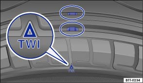 Fig. 113 Tread pattern: Wear indicator.Read and follow the introductory information and safety information first⇒Introduction to the subject
Most driving situations require as much tread depth as possible and similar tread depth for the tires on the front and rear wheels. This is especially true when driving in winter weather, at low temperatures and under wet conditions ⇒ .
In most countries the legally permissible minimum tread depth is 1/16 in. (1.6 mm), as measured in tread grooves next to the wear indicators. Please be sure to obey country-specific legal requirements.
Winter tires are no longer suitable for winter operation once the tread pattern is worn down to a depth of 3/16 in. (4.8 mm).
The tread depth of new tires can differ between tire models and manufacturers because of the different design features and tread patterns.
The 1/16 in. (1.6 mm) high wear indicators are molded into the bottom of the tread grooves of the original tires running across the treads ⇒ Fig. 113 . Several wear indicators are evenly spaced around the tire. Markings on the sides of the tires (for example TWI or symbols) show the position of the wear indicators.
Wear indicators show when the tires are worn down. The tires must be replaced no later than when the tread pattern is worn down to the wear indicators.
WarningWorn tires are dangerous and can cause loss of vehicle control including serious personal injuries.
Read and follow the introductory information and safety information first⇒Introduction to the subject
Wheel rim and tire damage is often difficult to see. Unusual vibrations or pulling to one-side can be an indication of tire damage ⇒ .
Tire wear depends on several factors, including:
Driving style – Fast cornering, hard acceleration and braking increase tire wear. If you experience increased tire wear under normal driving conditions, have the vehicle suspension checked by an authorized Volkswagen dealer or an authorized Volkswagen Service Facility.
Unbalanced wheels – The wheels on a new vehicle are balanced. When driving, however, various conditions can cause a wheel to become unbalanced. Unbalanced wheels can cause wear to the steering and suspension systems. Have all wheels rebalanced. A wheel must always be rebalanced if a new tire has been mounted.
Wheel alignment – Incorrect wheel alignment causes excessive and uneven tire wear, impairing vehicle safety. If you notice excessive or uneven tire wear, have the wheel alignment checked by an authorized Volkswagen dealer or an authorized Volkswagen Service Facility.
WarningUnusual vibrations or pulling to one side can indicate tire damage.
 Fig. 114 In the luggage compartment: Handwheel holding the spare wheel in place (if equipped).
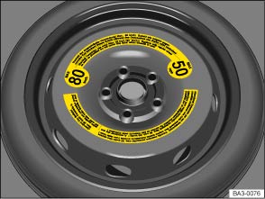 Fig. 115 In the luggage compartment: Compact spare wheel (if equipped).Read and follow the introductory information and safety information first⇒Introduction to the subject
Your vehicle may be equipped with a spare, a compact spare wheel, or a tire mobility set. For more information on the tire mobility set, see: ⇒ Tire mobility set .
If the replaced wheel does not fit in the spare wheel well, stow it securely in the luggage compartment on top of the floor covering.
If the spare is different from the road wheels, a compact spare wheel, for example, or if the road wheels are winter tires, the spare wheel must be used only in the event of a flat tire, only for a brief time, and only when driving with extra caution ⇒ .
Replace it with a tire matching the others on your vehicle as soon as possible.
Please heed the following:
Check the tire inflation pressure of the spare or compact spare whenever you check the tire pressure of the road wheels, at least once a month. Inflate a spare wheel to the cold tire pressure specified for the vehicle's road wheels on the tire pressure label; inflate a compact spare wheel to the cold tire pressure specified for the compact spare on the tire pressure label or on a separate label for the compact spare, if there is one.
WarningImproper use of a spare wheel or a compact spare wheel can cause loss of vehicle control, a crash or other accident, and serious personal injury.
NoteWhen the spare wheel or compact spare is being used, the TPMS indicator light can light up after a couple of minutes ⇒ Tire Pressure Monitoring System (TPMS) .If possible, attach the spare wheel, compact spare wheel, or the wheel you took off the vehicle securely in the luggage compartment.
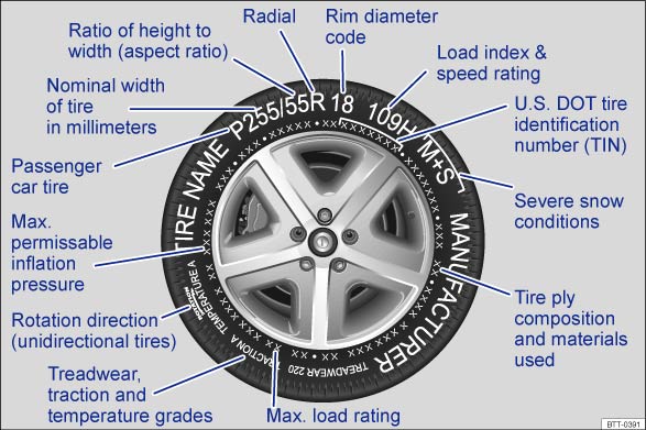 Fig. 116 International tire labeling.Read and follow the introductory information and safety information first⇒Introduction to the subject
Knowing about tire specifications makes it easier to choose the correct replacement tires. Radial tires have specifications marked on the sidewall.
| Tire labeling (example) | Meaning | |
|---|---|---|
| Brand, Logo | Manufacturer | |
| Tire name | Individual tire designation of the manufacturer. | |
| P255 / 55 R 18 | Dimensions: | |
| P | Tire application: Passenger car | |
| 255 | Nominal sidewall-to-sidewall width of tire in millimeters. | |
| 55 | Ratio of height to width (aspect ratio) | |
| R | Tire belt design letter code for radial. | |
| 18 | Rim diameter (in inches) | |
| 109 H | Load rating code ⇒ Load rating code and speed rating code ⇒ Speed rating code letter . | |
| XL | Indicates reinforced tire (heavy-duty) | |
| M+S or M/S | Indicates Mud and Snow capability (also M/S) ⇒ Winter tires . | |
| RADIAL TUBELESS | Tubeless radial tire. | |
| E4 ... | Labeling according to international regulations (E) including number of the approving country. The multi-digit approval number is listed next. | |
| DOT BT RA TY5 1709 | Tire identification number (TIN) – In some cases the manufacturing date is only on one side of the tire: | |
| DOT | The tire complies with the requirements of the United States Department of Transportation, responsible for issuing safety standards. | |
| BT | Identification letter of the manufacturing site. | |
| RA | Manufacturer information regarding tire dimensions. | |
| TY5 | Tire characteristics provided by the manufacturer. | |
| 1709 | Manufacturing date: 17th week in 2009. | |
| TWI | Marks the position of the treadwear indicator ⇒ Tread depth and tread wear indicators . | |
| Made in Germany | Country of manufacture. | |
| MAX LOAD 615 KG (1356 LBS) | United States maximum load rating per wheel. | |
| MAX INFLATION 350 KPA (51 PSI) | United States maximum permissible inflation pressure. | |
| ROTATION | Rotation direction (unidirectional tires) | |
| SIDEWALL 1 PLY RAYON |
Tire ply composition and materials used: 1 layer of rayon. |
|
|
TREAD 4 PLIES 1 RAYON + 2 STEEL + 1 NYLON |
Tire tread composition and materials used: In this example there are 4 layers under the tread: 1 layer of rayon, 2 layers of steel belt and 1 layer of nylon. |
|
|
Consumer information regarding comparison to specified base tires (standardized test procedure)⇒ ⇒ UTQG classification :
|
||
| TREADWEAR 220 | Relative service life expectancy of the tire referenced to a U.S.-specific standard test. | |
| TRACTION A | Traction rating under wet conditions (AA, A, B or C). | |
| TEMPERATURE A | Temperature stability of the tire at increased test bench speeds (A, B or C). | |
| Additional numbers found on the tire could either be tire manufacturer internal labels or country-specific labels (such as for Brazil and China). | ||
Unidirectional tires are designed to rotate only in one direction. Unidirectional tires have arrows on the sidewalls that show the direction of rotation. Make sure you mount the tire so that it rotates in the proper direction. The tire's performance with regard to hydroplaning, traction, noise, and wear is worse if it is not mounted in the proper direction of rotation.
If you have to mount a tire opposite to its proper direction of rotation, you must drive more carefully, since the tire is no longer being used as designed. This is particularly important on wet roads. You must replace or remount the tire as soon as possible in order to restore the correct direction of rotation.
The load index indicates the maximum permissible load per individual tire in pounds (kilograms).
911356 lbs (615 kg)921388 lbs (630 kg)931433 lbs (650 kg)951521 lbs (690 kg)971609 lbs (730 kg)981653 lbs (750 kg)991709 lbs (775 kg)1001763 lbs (800 kg)1011819 lbs (825 kg)1021874 lbs (850 kg)1031929 lbs (875 kg)1041984 lbs (900 kg)1102337 lbs (1060 kg)
The speed rating code letter indicates the maximum permissible road speed of the tires.
Pup to 93 mph (150 km/h)Qup to 99 mph (160 km/h)Rup to 106 mph (170 km/h)Sup to 112 mph (180 km/h)Tup to 118 mph (190 km/h)Uup to 124 mph (200 km/h)Hup to 130 mph (210 km/h)Vup to 149 mph (240 km/h)Zover 149 mph (240 km/h)Wup to 168 mph (270 km/h)Yup to 186 mph (300 km/h)
Some tire manufacturers label tires with a maximum permissible road speed above 149 mph (240 km/h) with the letter combination ZR.
WarningUsing incorrect or unmatched tires and/or wheels or improper tire and wheel combinations can lead to loss of control, collision and serious personal injury.
TIN represents the serial number of the tire.
Read and follow the introductory information and safety information first⇒Introduction to the subject
Winter tires improve the handling characteristics of your vehicle significantly when driving under wintry road conditions. Summer tires have less traction on snow and ice because of their design (width, rubber composition, tread design). Volkswagen strongly recommends that you always have winter tires or all-season tires installed on all 4 wheels on your vehicle, especially when winter road conditions are expected. Winter tires also improve the vehicle's braking performance and help reduce stopping distances during winter weather. Volkswagen recommends installing winter tires once temperatures are below +45 °F (+7 °C).
Winter tires are no longer suitable for winter driving once the tread pattern is worn down to a depth of 3/16 in (4.8 mm). In addition, winter tire performance decreases with age – independent of the tread profile depth.
.Winter tires are certified up to a top speed identified by speed rating code letters on the sidewall ⇒ Tire labeling .
In appropriately equipped vehicles, the speed warning can be set and changed in the Infotainment system by pressing the button followed by the
and Tires function keys ⇒ Menu and system settings .
Top speed rating and tire inflation pressure for V winter tires depend on the engine installed in your vehicle. Be sure to ask your authorized Volkswagen dealer or authorized Volkswagen Service Facility about the maximum permissible speed and the required tire inflation pressure for the winter tires that you plan to use.
Vehicles with all-wheel drive and standard road wheels have good forward motion and traction even under wintery road conditions. However, Volkswagen recommends installing winter tires or all season tires on all 4 wheels to improve handling as well as braking performance.
If you use snow chains, please read and heed information and directions ⇒ Snow chains .
WarningDriving faster than the maximum speed for which the winter tires on your vehicle were designed can cause sudden tire failure including a blowout and sudden deflation, loss of control, crashes and serious personal injuries.
Install summer tires promptly in the spring. Summer tires offer better handling characteristics for temperatures above +45 °F (+7 °C). They are quieter, do not wear as quickly, and reduce fuel consumption.The Tire Pressure Monitoring System must be recalibrated whenever you remove and remount or change any wheel or tire on the vehicle, even if the reinstalled or replacement wheels and tires are identical to those that were removed and even if the tire pressure does not change ⇒ Tire Pressure Monitoring System (TPMS) and recalibration through the Infotainment system .If necessary, ask your authorized Volkswagen dealer or authorized Volkswagen Service Facility about permissible winter tire dimensions.
Read and follow the introductory information and safety information first⇒Introduction to the subject
Obey local regulations as well as the applicable speed limits when driving with snow chains.
Snow chains improve forward motion, traction and braking characteristics under wintry conditions.
Snow chains may be used only on the front wheels and only in tire and wheel combinations that have been approved by Volkswagen. This applies even to all-wheel drive vehicles (4MOTION).
Please contact your authorized Volkswagen dealer or authorized Volkswagen Service Facility about appropriate wheel, tire and snow chain dimensions.
If possible, use only chains with low profile links that are not thicker than 37/64 in. (15 mm) including the tensioner.
Remove center hubcaps and decorative rim rings before installing snow chains ⇒ . However, for safety reasons, caps must be installed on the wheel bolts. These are available from authorized Volkswagen dealers and authorized Volkswagen Service Facilities.
For technical reasons, snow chains cannot be used on the compact spare ⇒ Spare wheel or compact spare wheel .
If you must use snow chains and have a compact spare wheel mounted, move the compact spare wheel to the rear axle if a front tire has to be replaced. The tire taken off the rear axle can then be used to replace the flat front tire. Be sure to install the unidirectional tires so that they will run in the proper direction. Volkswagen recommends installing the snow chains before mounting the wheel to the vehicle.
WarningUsing the wrong snow chains or installing snow chains improperly can cause accidents and severe personal injuries.
Note
Read and follow the introductory information and safety information first⇒Introduction to the subject
The combined weight (in excess of those standard items which may be replaced) of automatic transmission, electro-mechanical power steering, power brakes, power windows, power seats, radio, and heater, to the extent that these items are available as factory-installed equipment (whether installed or not).
The ratio of sidewall height to tire width, expressed as a percentage. A number of 50 (0.5:1 or 50%) means that the cross-sectional height is 50% of the tread width. A shorter sidewall can improve steering response and provide better overall handling, for example, on dry pavement.
The part of a tire made of steel wires, wrapped or reinforced by ply cords, with the shape and structure to ensure proper fit to the wheel rim.
A breakdown of the bond between components in the bead.
The tire structure, except tread and sidewall rubber which, when inflated, bears the load.
The breaking away of pieces of the tread or sidewall.
The strands of material forming the plies in the tire.
The parting of cords from adjacent rubber compounds.
Any parting within the tread, sidewall, or inner liner of the tire extending to cord material.
The tire pressure recommended by the vehicle manufacturer for a tire of a specified size that has not been driven for more than a couple of miles (kilometers) at low speeds in the 3 hour period before the tire pressure is measured or adjusted.
The weight of a motor vehicle with standard equipment including the maximum capacity of fuel, oil, and coolant, air conditioner, and additional weight of optional equipment.
A tire designed to operate at higher loads and at higher inflation pressures than the corresponding standard tire.
The load-carrying capacity of a single axle system, measured where the tire contacts the ground.
The maximum loaded weight of the vehicle.
The space between 2 adjacent tread ribs.
The maximum load that a tire is rated to carry for a given inflation pressure. You may not find this information on all tires because it is not required by law.
The load rating for a tire at the maximum permissible inflation pressure for that tire.
The total of:
The maximum cold inflation pressure to which a tire may be inflated. Also called maximum inflation pressure.
Means 150 lbs (68 kilograms) times the number of occupants seated in the vehicle up to the total seating capacity of your vehicle.
The placement of passengers in a vehicle.
The diameter of a new, properly inflated tire.
Total width measured at the exterior sidewalls of an inflated tire, including the additional width of labeling, decorations, or protective bands or ribs.
A tire intended for use on passenger cars, multipurpose passenger vehicles, and trucks, that have a gross vehicle weight rating (GVWR) of 10,000 pounds or less.
A layer of rubber-coated parallel cords.
A parting of rubber compound between adjacent plies.
A mechanical device made of rubber, chemicals, fabric, and steel or other materials, that, when mounted on an automotive wheel, provides the traction and contains the gas or fluid that sustains the load.
The combined weight of installed regular production options weighing over 5 lbs (2.3 kg) more than the standard items they replace, and not previously considered as curb weight or accessory weight. These include, for example, heavy-duty brakes, ride levelers, roof rack, heavy-duty battery, and special trim.
A pneumatic tire in which the ply cords that extend to the beads are laid at substantially 90 degrees to the centerline of the tread.
The tire pressure recommended by the vehicle manufacturer for a tire of a specified size that has not been driven for more than a couple of miles (kilometers) at low speeds in the 3 hour period before the tire pressure is measured or adjusted.
A tire designed to operate at higher loads and at higher inflation pressures than the corresponding standard tire.
The outer edge of a wheel upon which the tire beads are seated.
The nominal diameter of the wheel's tire bead seating surface. If you change your wheel size, to wheels of a different diameter, you will have to purchase new tires to match the new wheels.
Designation means rim diameter and width.
The industry or manufacturer's designation for a rim by style or code.
The nominal distance between wheel rim flanges.
The linear distance between the exteriors of the sidewalls of an inflated tire, excluding elevations due to labeling decoration, or protective bands.
The portion of a tire between the bead and the tread.
The parting of the rubber compound from the cord material in the sidewall.
A standardized letter code indicating the maximum speed at which a tire is designed to be driven for extended periods of time. The ratings range from 93 mph or 150 km/h (P) to 186 mph or (300 km/h) Y.
The speed rating letter code, where applicable, is molded on the tire sidewall ⇒ Tire labeling . You may not find this information on all tires because it is not required by law.
A system that detects when at least one of a vehicle's tires is underinflated and illuminates a low tire-pressure warning light.
The portion of a tire that normally touches the road.
A tread section running circumferentially around a tire.
Tire failure caused by the tread pulling away from the tire carcass.
Raised areas within the main tread grooves that show, visually, when tires are worn and near the end of their useful life ⇒ Tread depth and tread wear indicators .
A tire information system developed by the U.S. National Highway Traffic Safety Administration (NHTSA) that is designed to help buyers compare tires. UTQG is not a safety rating, nor is it a guarantee that a tire will last for a certain number of miles or perform a certain way. It gives tire buyers more information to compare with factors such as price, brand loyalty and dealer recommendations. Under UTQG, tires are graded by the tire manufacturers in 3 areas: tread wear, traction and temperature resistance. UTQG information is molded into the tire sidewalls.
A tire's serial number. It begins with the letters DOT (Department of Transportation) and indicates that the tire meets all federal standards. The next 2 numbers or letters indicate the plant where the tire was manufactured. The last 4 numbers represent the week and year of manufacture.
For example, the numbers 1709 mean that the tire was produced in the 17th week of 2009. Any other numbers are marketing codes used by the tire manufacturer. This information is used to help identify affected consumers if a tire defect requires a recall.
The total rated cargo, luggage and passenger load. Passenger load is 150 lbs (68 kilograms) times the vehicle's total seating capacity (as listed on the label inside the driver door).
The load on an individual tire that is determined by taking each axle's share of the maximum loaded vehicle weight (GAWR) and dividing by 2.
The load on an individual tire that is determined by taking each axle's share of the curb weight, accessory weight, and normal occupant weight (distributed according to the table below) and dividing by 2.
Wheel rim diameter and width.
| Designated seating capacity, number of occupants | Vehicle normal load, number of occupants | Occupant distribution in a normally loaded vehicle |
|---|---|---|
| 2, 3, or 4 | 2 | 2 in front |
| 5 | 3 | 2 in front, 1 in back |
Read and follow the introductory information and safety information first⇒Introduction to the subject
There are limits to the load any vehicle or any tire can carry. A vehicle that is overloaded will not handle well and is more difficult to stop. Overloading can damage important parts of the vehicle. Overloading can also lead to blowout, sudden loss of pressure or other tire failure that can cause loss of control.
Your safety and the safety of your passengers depends on making sure that load limits are not exceeded. Vehicle load includes everybody and everything in and on the vehicle. These load limits are technically referred to as the vehicle's Gross Vehicle Weight Rating (GVWR).
The GVWR includes the weight of the basic vehicle, all factory-installed and other accessories, a full tank of fuel, oil, coolant and other fluids plus maximum load. The maximum load includes the number of passengers that the vehicle is intended to carry (seating capacity) with an assumed weight of 150 lbs (68 kg) for each passenger at a designated seating position and the total weight of any luggage in the vehicle. If you tow a trailer, the weight of the trailer hitch and the tongue weight of the loaded trailer must be included as part of the vehicle weight. At altitudes above 3000 ft (1000 m), combined towing weight (vehicle plus trailer) must be reduced by 10% for every 3000 ft (1000 m).
The Gross Axle Weight Rating (GAWR) is the maximum load that can be carried at each of the vehicle's 2 axles (by the front or rear tires). GVWR and GAWR are listed on the safety compliance label on the driver door jamb. Because there is an upper limit to your vehicle's total weight (GVWR), the weight of whatever is being carried (including the weight of a trailer hitch and the tongue weight of the loaded trailer) is also limited. More passengers, or passengers who are heavier than the assumed 150 lbs (68 kg), mean that less weight can be carried as luggage or other cargo. The tire pressure label on your Volkswagen also lists the maximum combined weight of all of the occupants and luggage or other cargo that the vehicle can carry.
WarningOverloading a vehicle can cause loss of vehicle control, a crash or other accident, serious personal injury, and even death.
Read and follow the introductory information and safety information first⇒Introduction to the subject
Never overload tires. The following example illustrates how to determine the combined weight of all vehicle occupants and luggage or other vehicle payloads. Never overload the vehicle!
| Steps for Determining Correct Load Limit: | |
|---|---|
| 1. | Locate the statement THE COMBINED WEIGHT OF OCCUPANTS AND CARGO SHOULD NEVER EXCEED XXX KG OR XXX LBS on your vehicle's placard (tire inflation pressure label) ⇒ Tire inflation pressure . |
| 2. | Determine the combined weight of the driver and passengers that will be riding in your vehicle. |
| 3. | Subtract the combined weight of the driver and passengers from XXX kg or XXX lbs. |
| 4. |
The resulting figure equals the available amount of cargo and luggage load capacity. For example, if the XXX amount equals 1400 lbs. and there will be five 150 lb. passengers in your vehicle, the amount of available cargo and luggage load capacity is 650 lbs. (1400-750 (5 x 150) = 650 lbs.) |
| 5. | Determine the combined weight of luggage and cargo being loaded on the vehicle. That weight may not safely exceed the available cargo and luggage load capacity calculated in Step 4. |
| 6. | If your vehicle is capable of towing a trailer: The load from your trailer will be transferred to your vehicle. Consult this manual to determine how this reduces the available cargo and luggage load capacity of your vehicle. |
| Check the tire sidewall to determine the load index specified for the tire. | |
Read and follow the introductory information and safety information first⇒Introduction to the subject
Uniform Tire Quality Grading (UTQG): Quality grades can be found where applicable on the tire sidewall between the tread shoulder and maximum section width. Example:
For example: Treadwear 200, Traction AA, Temperature A.
All passenger car tires must conform to Federal Safety Requirements in addition to these grades.
The treadwear grade is a comparative rating based on the wear rate of the tire when tested under controlled conditions on a specified government test course.
For example, a tire graded 150 (Treadwear-value 150) would wear one-and-one-half (1 1/2) times as well on the government course as a tire graded 100.
The relative performance of tires depends upon the actual conditions of their use, however, and may depart significantly from the norm due to variations in driving habits, service practices and differences in road characteristics and climate.
The traction grades, from highest to lowest, are AA, A, B, and C. Those grades represent the tire's ability to stop on wet pavement as measured under controlled conditions on specified government test surfaces of asphalt and concrete. A tire marked C may have poor traction performance ⇒ .
The temperature grades are A (the highest), B, and C representing the tire's resistance to the generation of heat, and its ability to dissipate heat when tested under controlled conditions on a specified indoor laboratory test wheel.
Sustained high temperature can cause the material of the tire to degenerate and reduce tire life, and excessive temperature can lead to sudden tire failure.
The grade C corresponds to a level of performance which all passenger car tires must meet under the Federal Motor Vehicle Safety Standard No. 109. Grades B and A represent higher levels of performance on the laboratory test wheel than the minimum required by law ⇒ .
WarningThe traction grade assigned to this tire is based on straight-ahead braking traction tests, and does not include acceleration, cornering, hydroplaning or peak traction characteristics.WarningThe temperature grade for this tire is established for a tire that is properly inflated and not overloaded. Excessive speed, underinflation or excessive loading, either separately or in combination, can cause heat buildup and possible tire failure.
Introduction to the subjectIn this chapter you will find information on the following subjects:⇒ Indicator light (telltale) ⇒ Tire Pressure Monitoring System (TPMS) and recalibration through the Infotainment system
Your vehicle's Tire Pressure Monitoring System (TPMS) uses the Anti-lock Brake System (ABS) sensors to indirectly check the tire pressure of all 4 tires while you are driving. The sensors monitor the tread circumference (rolling circumference) and vibration characteristics of the individual tires. TPMS warns if there is a significant loss of pressure in one or more tires while the vehicle is moving. Pressure loss is signaled by the indicator light (described below) as well as by acoustic warnings and text warnings in the instrument cluster display if your vehicle has this display Infotainment system or the Multi-Function Display (MFD).
The original benchmark pressure is the recommended maximum load cold tire inflation pressure for the tires that come with your vehicle. This pressure is listed on the tire pressure label on the driver door jamb ⇒ Tire inflation pressure . After adjusting the tire pressures in all 4 tires, you must confirm and store the new cold inflation pressures through the Infotainment system, which changes the benchmark pressure to match the current pressure of the tires on your vehicle ⇒ Tire Pressure Monitoring System (TPMS) and recalibration through the Infotainment system .
Recalibrating the TPMS to reset the benchmark cold tire inflation pressure is explained on ⇒ Tire Pressure Monitoring System (TPMS) and recalibration through the Infotainment system .
WarningIncorrect tire pressures and/or underinflation can cause sudden tire failure, loss of control, collision, serious personal injury or even death.
WarningImproper recalibration can cause the TPMS to give false warnings or to give no warning despite dangerously low tire pressure ⇒ Tire Pressure Monitoring System (TPMS) and recalibration through the Infotainment system .Underinflation increases fuel consumption and tire wear.Do not rely solely on the Tire Pressure Monitoring System. Check your tires regularly to make sure they are properly inflated and have no signs of damage, such as punctures, cuts, cracks, and blisters. Remove any objects that become embedded in the tire tread but have not penetrated into the body of tire itself.When you take delivery of the vehicle, the Tire Pressure Monitoring System is calibrated for the factory-recommended cold tire inflation pressure for the tires on your vehicle, as shown on the label inside the driver door ⇒ Tire inflation pressure .
If you have work done on your wheels or tires, inform the workshop that the vehicle is equipped with a Tire Pressure Monitoring System (TPMS).New tires may expand slightly the first time they are driven at high speeds, which can trigger a tire pressure warning. Remember that tire pressure can only be properly measured when the tire is cold ⇒ Tire inflation pressure .Only replace old tires with tires that have been approved by Volkswagen for your vehicle type.
Read and follow the introductory information and safety information first⇒Introduction to the subject
| Lights up |
Possible cause or meaning ⇒
|
Proper response |
|---|---|---|
|
|
Lights up and a chime may also sound. The inflation pressure of one or more tires is significantly lower than the benchmark pressure set by the driver or a tire has structural damage. Depending on vehicle equipment, a message may also appear in the instrument cluster display. |
Reduce speed immediately! Avoid fast cornering and hard braking! Check the condition and inflation pressure of all tires. Have damaged tires replaced. |
| Flashes |
Possible cause or meaning ⇒
|
Proper response |
|---|---|---|
|
|
Flashes for about 70 seconds and then stays on: System malfunction. |
Check and, if necessary, adjust the tire inflation pressure in all 4 tires. If the tire pressure is correct, switch the ignition off and back on. If the indicator light flashes again and then stays on or does not go out after checking and adjusting the air pressure in all 4 tires and recalibrating, take the vehicle to an authorized Volkswagen dealer or an authorized Volkswagen Service Facility. Have the system checked. |
When the ignition is switched on, several warning and indicator lights come on briefly for a function check. They go out after a few seconds.
WarningIncorrect tire pressures and/or underinflation can cause sudden tire failure, loss of control, collision, serious personal injury, or even death.
WarningImproper recalibration can cause the TPMS to give false warnings or to give no warning despite dangerously low tire pressure ⇒ Tire Pressure Monitoring System (TPMS) and recalibration through the Infotainment system .WarningFailure to heed warning lights and instrument cluster text messages can cause the vehicle to break down in traffic and result in a collision and serious personal injury.
NoteFailure to heed warning lights or text WARNINGS can result in vehicle damage.If the ignition is switched on, an acoustic warning sounds when low tire pressure is detected. An acoustic warning also sounds if a system malfunction is detected.Driving for a longer period of time on rough roads or with a dynamic and sporty style can make the TPMS system temporarily unavailable. The indicator light will come on, signaling a malfunction, but will go out again once the road condition or driving style changes.
Read and follow the introductory information and safety information first⇒Introduction to the subject
Your vehicle's Tire Pressure Monitoring System (TPMS) indirectly checks the tire pressure of all 4 tires while you are driving by using the Anti-lock Brake System (ABS) sensors to monitor the tread circumference (rolling circumference) and vibration characteristics of the individual tires.
The tread circumference of a tire can change:
The Tire Pressure Monitoring System (TPMS) may not react at first or may not react at all when you are driving in a sporty manner, or on snow-covered or unpaved roads, when you are driving with snow chains, or in certain other situations. A change in the tread circumference of a tire is signaled by the Tire Pressure Monitoring System indicator in the instrument cluster (telltale).
The tire pressure recommended for the tires originally installed on the vehicle is on a sticker on the driver door jamb ⇒ Tires and wheels .
Each tire, including the spare (if provided), should be checked monthly when cold and inflated to the inflation pressure recommended by the vehicle manufacturer on the vehicle placard or tire inflation pressure label. (If your vehicle has tires of a different size than the size indicated on the vehicle placard or tire inflation pressure label, you should determine the proper tire inflation pressure for those tires.)
As an added safety feature, your vehicle has been equipped with a Tire Pressure Monitoring System (TPMS) that illuminates a low tire pressure telltale when one or more of your tires is significantly underinflated. Accordingly, when the low tire pressure telltale illuminates, you should stop and check your tires as soon as possible, and inflate them to the proper pressure. Driving on a significantly underinflated tire causes the tire to overheat and can lead to tire failure. Underinflation also reduces fuel efficiency and tire tread life, and may affect the vehicle's handling and stopping ability.
Please note that the TPMS is not a substitute for proper tire maintenance, and it is the driver's responsibility to maintain correct tire pressure, even if underinflation has not reached the level to trigger illumination of the TPMS low tire pressure telltale.
Your vehicle has also been equipped with a TPMS malfunction indicator to indicate when the system is not operating properly. The TPMS malfunction indicator is combined with the low tire pressure telltale. When the system detects a malfunction, the telltale will flash for approximately one minute and then remain continuously illuminated. This sequence will continue upon subsequent vehicle start-ups as long as the malfunction exists.
When the malfunction indicator is illuminated, the system may not be able to detect or signal low tire pressure as intended. TPMS malfunctions may occur for a variety of reasons, including the installation of replacement or alternate tires or wheels on the vehicle that prevent the TPMS from functioning properly. Always check the TPMS malfunction telltale after replacing one or more tires or wheels on your vehicle to ensure that the replacement or alternate tires and wheels allow the TPMS to continue to function properly.
Resetting the tire pressures in the Infotainment system resets the benchmark tire pressure used by the TPMS to the current tire pressure in the tires based on the circumference of the tires.
The recalibration must be performed each time the tire pressure in one or more tires has been adjusted or after one or more tires has been changed, exchanged, or repaired. The new tire pressures are stored in the system only after at least 20 minutes of normal driving.
If you have reset the benchmark tire pressure when your tires do not have the correct tire pressure, this will prevent the TPMS from working properly. It may then give false warnings or may not give any warning even if the tire pressure is too low.
For this reason, it is vital to make certain that all 4 tires are inflated to the correct pressure when they are cold before calibrating the system. Cold tire tires are tires that have not been driven more than a couple of miles (kilometers) at low speed within the last 3 hours.
During normal vehicle operation, the system calibrates itself to the tires installed and the changed tire pressures. The calibrated values are stored and monitored after a long journey at various speeds.
If the wheels are loaded more heavily than normal, for example, if the vehicle is carrying heavy load, the tire pressure must be raised to the recommended full-load tire pressure before recalibaration ⇒ Tires and wheels .
WarningIncorrect recalibration can cause the TPMS to give false warnings or to give no warning despite dangerously low tire pressure. Make certain the tire inflation pressure of all tires is correct before recalibrating the system.WarningIncorrect tire pressure can cause sudden tire failure, loss of vehicle control and serious personal injury.
The Tire Pressure Monitoring System stops working if there is an ESC/ABS malfunction ⇒ Braking and parking .After a low tire pressure warning, the vehicle must stand and must not be driven for at least 1 minute before the new benchmark tire pressures can be stored.
Introduction to the subjectIn this chapter you will find information on the following subjects:⇒ Storage compartments in the doors ⇒ Storage compartment on the driver side ⇒ Eyeglass storage compartment in the overhead console ⇒ Storage compartment in the front center console ⇒ Coin holders in the front center console (Golf, Golf GTI) ⇒ Storage compartment in the front center armrest (Golf, Golf GTI) ⇒ Glove compartment ⇒ Storage compartment under the front seat ⇒ Other storage compartments
Store only lightweight or small objects in storage compartments.
Depending on options, there may be a factory-installed AUX-in jack and/or USB port
in the front center console storage compartment.
WarningLoose objects can be thrown around the inside of the vehicle when the vehicle is moving, especially during sudden maneuvers and hard braking. This can cause serious personal injuries and even make the driver lose control of the vehicle.
WarningObjects in the driver footwell can prevent the pedals from moving freely. This can cause loss of vehicle control and increase the risk of serious personal injuries.
WarningSome kinds of cigarette lighters can be lit unintentionally, or crushed causing a fire that can result in serious burns and vehicle damage.
Note
The ventilation slots in the luggage compartment must not be blocked so that stale air can escape from the vehicle.
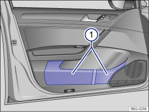 Fig. 117 In the driver door: Storage compartment.Read and follow the introductory information and safety information first⇒Introduction to the subject
There is a storage compartment in each vehicle door ⇒ Fig. 117① .
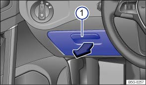 Fig. 118 On the driver side: Storage compartment.Read and follow the introductory information and safety information first⇒Introduction to the subject
To open the compartment, pull the handle ⇒ Fig. 118① in the direction of the arrow.
To close, push the lid up until it latches.
On some vehicles, there is a holder for SD cards on the inside of the storage compartment lid.
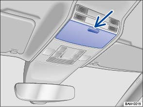 Fig. 119 In the overhead console: Storage compartment.Read and follow the introductory information and safety information first⇒Introduction to the subject
Your vehicle may have a storage compartment that can be used for storing eyeglasses or other light objects.
To open, briefly press and release the button ⇒ Fig. 119 (arrow) on the storage compartment cover.
To close, push the lid up until it latches.
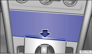 Fig. 120 In the front center console: Storage compartment.Read and follow the introductory information and safety information first⇒Introduction to the subject
To open, briefly press the lower edge of the cover in the direction of the arrow ⇒ Fig. 120 .
To close, press the lid down completely.
The storage compartment in the front center console may have an AUX-in jack and/or a USB port
⇒BookletInfotainment System,.
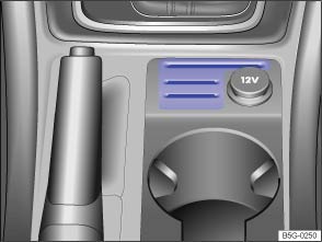 Fig. 121 In the front center console: Coin holders.Read and follow the introductory information and safety information first⇒Introduction to the subject
Depending on equipment, the lower part of the front center console ⇒ Fig. 121 may have slots for storing coins.
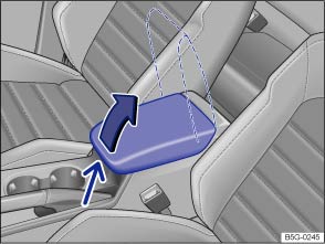 Fig. 122 In the front center armrest: Storage compartment.Read and follow the introductory information and safety information first⇒Introduction to the subject
Depending on equipment, your vehicle may have a storage compartment under the front center armrest.
To open, push the release button (small arrow) and lift the center armrest up as far as it will go in the direction of the large arrow ⇒ Fig. 122 .
To close, push the center armrest down.
WarningThe center armrest can restrict the driver's arm movement and cause crashes and serious personal injury.
WarningNever let a passenger, especially a child, ride on the center armrest.There may be a 12 volt socket ⇒ Power outlets or a phone holder in the front center armrest storage compartment ⇒BookletInfotainment System,.
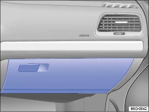 Fig. 123 On the passenger side: Glove compartment.
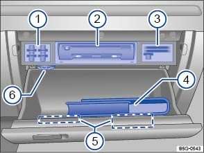 Fig. 124 Inside the glove compartment.Read and follow the introductory information and safety information first⇒Introduction to the subject
Key to ⇒ Fig. 124 :
SD card holdersInfotainment system accessories (if equipped) ,ChapterInfotainment SystemCard holders and coin holderOwner's ManualAdditional holders for coins, cards, or sunglassesAir vent ⇒ Heating and air conditioning To open, pull the handle ⇒ Fig. 123 .
To close, push the lid up.
Vehicles equipped with an Infotainment system may have a CD player, SD card readers, or other Infotainment System accessories ⇒ Fig. 124② in the glove compartment. See ,ChapterInfotainment System for further information.
If the vehicle is not equipped with an Infotainment system, there is a slot for the Owner's Manual in the upper part of the glove compartment. Always keep the Owner's Manual in this slot or in the glove compartment as shown in ⇒ Fig. 124④ .
Depending on vehicle equipment, there may be holders for SD cards ⇒ Fig. 124① , other types of cards ③, and a coin holder in the upper part of the glove compartment.
There may also be additional holders for coins, cards, or sunglasses in the glove compartment cover ⑤.
There is an air vent ⇒ Fig. 124⑥ in the glove compartment. Cool air can be directed into the glove compartment if the air conditioner is on. Open or close the air vent by turning it.
WarningAn open glove compartment door can increase the risk of serious injury during sudden braking or driving maneuvers or in a crash.
NoteIn some vehicle models, design considerations have made it necessary to have openings in the glove compartment behind the Owner's Manual slot, for example. Small items may fall through these openings and get behind the instrument panel. This can cause unusual noises and damage the vehicle. Never put any small objects in the glove compartment for this reason.
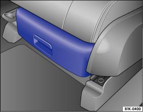 Fig. 125 Under the driver seat: Storage compartment.Read and follow the introductory information and safety information first⇒Introduction to the subject
Some vehicles are equipped with a storage compartment ⇒ Fig. 125 under the driver or passenger seat. A first aid kit can be stored in this storage compartment.
To open: Grasp the opening handle and pull the storage compartment out.
To close: Push the storage compartment toward the seat until it engages securely.
WarningAn open storage compartment can interfere with the pedals and cause accidents and severe personal injuries.
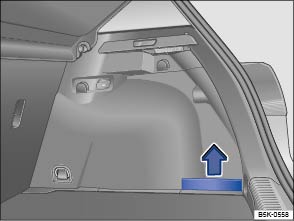 Fig. 126 In the luggage compartment: Side storage compartment.Read and follow the introductory information and safety information first⇒Introduction to the subject
Additional storage compartments are located in the sides of the luggage compartment. The side panels can be removed by pulling upward in the direction of the arrow ⇒ Fig. 126 to make room for larger objects in the luggage compartment.
The vehicle tool kit may be stored in this compartment ⇒ Vehicle tool kit .
WarningClothes or other items on the luggage compartment cover behind the rear seat backrest may limit visibility and cause accidents and severe personal injuries.
NoteThe maximum load for each coat hook is 5 lbs. (2.5 kg).
Introduction to the subjectIn this chapter you will find information on the following subjects:⇒ Cup holders in the front center console ⇒ Cup holders in the rear center armrest ⇒ Cup holders in the rear trim
There is a place for bottles in the open compartments in the driver and passenger doors. The bottle volume must not exceed 16.9 oz (0.5 liter) ⇒ .
WarningImproper use of beverage holders can cause injuries.
WarningHot or freezing temperatures in the passenger compartment can cause closed bottles to explode or break.
WarningBottles and other things can fall into the driver's footwell and interfere with the pedals while driving.
NoteNever put open drinks in the cup holders when the vehicle is moving. The drinks can spill and damage the vehicle, including the electrical system.Some cup holder inserts can be removed for cleaning.
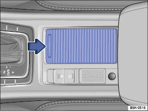 Fig. 127 In the front center console: Opening the cup holder cover (if equipped).
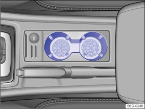 Fig. 128 In the front center console: Cup holders (without a cover).Read and follow the introductory information and safety information first⇒Introduction to the subject
Some models are equipped with a cover for the cup holders.
To open, pull the cover to the rear ⇒ Fig. 127 (arrow).
To close, push the cover forward (opposite direction of the arrow).
For vehicles without a cover, place the drink in the cup holder ⇒ Fig. 128 .
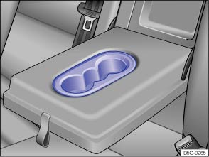 Fig. 129 Cup holders in the rear center armrest (version 1).
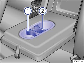 Fig. 130 Cup holders in the rear center armrest (version 2).Read and follow the introductory information and safety information first⇒Introduction to the subject
Your vehicle may be equipped with cup holders in the rear center armrest.
To open, fold the center armrest down.
Some cup holders have inserts that can be positioned to hold beverages of different sizes ⇒ Fig. 130 . To adjust the cup holder to the size of the cup, pull the inserts ① or ② upward and reposition them to fit the size of the cup.
To close, fold the center armrest up.
WarningAlways keep the armrest folded up when the vehicle is moving to reduce the risk of injury.
Some cup holder designs allow you to adjust to the size of the cup by turning the inserts 180 degrees.
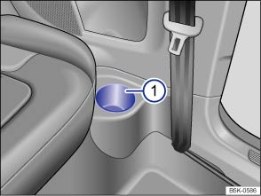 Fig. 131 In the trim next to the rear seats (2-door models only): Cup holder.Read and follow the introductory information and safety information first⇒Introduction to the subject
Some 2-door vehicles are equipped with open cup holders in the trim next to the rear seats ⇒ Fig. 131① .
Introduction to the subjectIn this chapter you will find information on the following subjects:⇒ 12 Volt sockets in the vehicle
Electrical devices can be connected to the vehicle 12 Volt sockets.
The connected devices must be in good working order.
WarningImproper use of electrical sockets and electrical devices may start a fire and cause severe personal injury.
Note
Please turn off the engine when you stop for any length of time.The vehicle battery will drain if you use electrical equipment when the engine is not running.Unshielded devices may interfere with radio reception or the vehicle's electrical system.Operating electrical devices near the windshield-integrated antenna may interfere with AM radio reception.
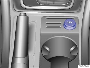 Fig. 132 In the lower center console: 12 Volt socket (vehicles with parking brake lever).
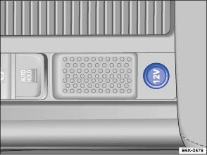 Fig. 133 In the lower center console: 12 Volt socket (vehicles with electronic parking brake).Read and follow the introductory information and safety information first⇒Introduction to the subject
| Socket | Maximum power draw |
|---|---|
| 12 Volts | 120 watts |
The maximum power draw at any one socket must never be exceeded. Electrical devices should have information on them that says how much power they draw.
If 2 or more electrical devices are connected at the same time, the total power draw of all connected devices must never be more than 190 watts ⇒ .
The 12 Volt socket works only when the ignition is switched on.
If the ignition is on but the engine is not running, the vehicle battery will be drained by any device that is plugged in and turned on. For this reason, never use the electrical sockets unless the engine is running.
To help prevent damage from voltage fluctuations, switch off all electrical devices connected to a 12 Volt socket before switching the ignition on or off or starting the engine.
The vehicle may have 12 Volt sockets at the following places:
Note
Unshielded devices may interfere with radio reception or the vehicle's electrical system.
Introduction to the subjectIn this chapter you will find information on the following subjects:⇒ Indicator lights ⇒ Vehicle key positions in the ignition switch ⇒ Starter button ⇒ Starting the engine ⇒ Stopping the engine ⇒ Electronic immobilizer
Explanatory notes in this section regarding automatic transmissions also apply to the DSG automated transmission.
If an unauthorized vehicle key is used or the system malfunctions, a message may appear in the instrument cluster display. The engine cannot be started.
For technical reasons, never try to push-start or tow-start the vehicle. Jump-start the vehicle instead while following proper and safe procedures.
WarningSwitching off the engine while the vehicle is moving can make the vehicle harder to stop and result in loss of vehicle control, leading to collisions and severe personal injuries.
WarningTo reduce the risk of serious personal injury when starting and running the vehicle's engine:
WarningTo reduce the risk of serious personal injury when you leave the vehicle.
WarningThe vehicle exhaust system and the catalytic converter or diesel particulate filter get very hot. They can cause fires and serious personal injury.
Read and follow the introductory information and safety information first⇒Introduction to the subject
| Lights up | Possible cause | Proper response |
|---|---|---|
|
|
Brake pedal not depressed. | Apply the brake pedal to start the engine ⇒ Braking and parking . |
| Flashes | Possible cause | Proper response |
|---|---|---|
|
|
The release button in the selector lever did not engage. Vehicle movement is prevented. | Engage the selector lever release button ⇒ Automatic Shift Lock (ASL) . |
When the ignition is switched on, several warning and indicator lights come on briefly for a function check. They go out after a few seconds.
WarningFailure to heed warning lights and instrument cluster text messages can cause the vehicle to break down in traffic and result in a collision and serious personal injury.
NoteFailure to heed warning lights or text WARNINGS can result in vehicle damage.
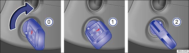 Fig. 134 In the ignition switch: Vehicle key positions.Read and follow the introductory information and safety information first⇒Introduction to the subject
If there is no vehicle key in the ignition, the steering column is locked.
Vehicle key position ⇒ Fig. 134
 Ignition switched off. Steering column lock engaged. The vehicle key can be removed.Ignition is switched on. Steering column lock can be released.Start the engine. When the engine starts, release the vehicle key. When released, the vehicle key returns to position ①.
If an unauthorized vehicle key has been inserted into the ignition switch, it can be removed as follows:
If you leave the ignition on and open the driver door, a warning message may appear in the instrument cluster. In addition, you may also hear an acoustic warning. This warning reminds you to switch off the ignition before leaving the vehicle ⇒ .
WarningImproper use of vehicle keys can result in serious personal injury.
NoteLeaving the key in the ignition for a long time when the engine is not running will drain the vehicle battery.
Leaving the selector lever for a long period of time in any position other than Park (P) when the ignition is switched off can drain the vehicle battery.On automatic transmission vehicles, the vehicle key can be removed from the ignition switch only when the transmission is in Park (P). You may have to press the release button on the transmission selector lever to put the lever into Park (P).
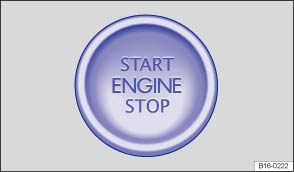 Fig. 135 In the lower center console: Starter button for the Keyless Access system.
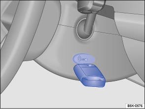 Fig. 136 Hold the remote control vehicle key to the right of the steering column: Emergency starting feature.Read and follow the introductory information and safety information first⇒Introduction to the subject
On appropriately equipped vehicles, the vehicle can be started and stopped with the starter button in the lower center console ⇒ Fig. 135 .
The starter button can only be used when an authorized vehicle key is in the vehicle.
When leaving the vehicle, the electronic steering column lock is activated when the ignition is switched off and the driver door is opened ⇒ Steering .
.If you push the starter button while an authorized remote control vehicle key is in the passenger compartment, but a driver information message appears in the instrument cluster indicating that the vehicle key is not detected, the remote control vehicle key battery is weak or dead. You can still start the engine using the Emergency start feature.
If the engine does not switch off by briefly pressing the starter button, emergency shut-off is necessary:
.If no authorized remote control vehicle key is identified in the passenger compartment after the engine has been switched off, the engine cannot be restarted. A related message is shown in the instrument cluster display.
WarningUnintended vehicle movement can cause serious personal injury.
WarningImproper use of vehicle keys can result in serious personal injury.
If the ignition is switched on or the engine is running and the driver door is opened, a chime sounds. The chime is also a reminder to switch off the engine and turn off the ignition before leaving and locking the vehicle from the outside.Leaving the ignition on for a long time when the engine is not running will drain the vehicle battery and the engine may not start.
Always switch off the ignition before leaving the vehicle. Read and follow any information in the instrument cluster display.
Read and follow the introductory information and safety information first⇒Introduction to the subject
| Please perform these steps only in the order listed. | ||
|---|---|---|
| Step | Vehicles without Keyless Access | Vehicles with Keyless Access |
| 1. | Depress the brake pedal and hold it down until step 5 is completed. | |
| 1 a. | Manual transmission: Fully depress clutch pedal and hold until the engine has started. | |
| 2. | Make sure the transmission is in Park (P) or Neutral (N). | |
| 3. | Turn the vehicle key to position ⇒ Fig. 134② – do not depress the accelerator pedal. | Briefly press the starter button ⇒ Fig. 135 – do not depress the accelerator pedal. An authorized vehicle key must be inside the vehicle in order to start the engine. |
| 4. | When the engine starts, release the vehicle key. | When the engine starts, release the starter button. |
| 5. | If the engine does not start, switch off the ignition and start again after about 1 minute. | If the engine does not start, switch off the ignition and start again after about 1 minute. Use the emergency start feature if necessary ⇒ Emergency start feature . |
| 6. | Release the parking brake when you are ready to start driving ⇒ Braking and parking . | |
WarningNever leave the vehicle unattended with the engine running, especially when it is in gear. The vehicle could move suddenly or some other unexpected event could occur, resulting in property damage, fire, or personal injury.WarningStarting fluids can explode and can cause a run-away vehicle condition.
Note
Do not let your vehicle warm up while standing; instead, start driving right away after making sure that you have good visibility through all windows. This will help the engine reach operating temperature faster and keep down emissions.Major consumers of electricity are temporarily switched off when the engine is being started.After starting a cold engine, there may be increased operating noises for a few seconds. This is normal and harmless.
Read and follow the introductory information and safety information first⇒Introduction to the subject
| Please perform these steps only in the order listed. | ||
|---|---|---|
| Step | Vehicles without Keyless Access | Vehicles with Keyless Access |
| 1. |
Bring the vehicle to a complete stop ⇒ .
|
|
| 2. | Depress and hold down the brake pedal until step 4 is completed. | |
| 3. | Automatic transmission: Shift the transmission into Park (P). | |
| 4. | Apply the parking brake to help prevent the vehicle from moving ⇒ Braking and parking . | |
| 5. | Turn the vehicle key to position ⇒ Fig. 134⓪ in the ignition switch. | Briefly press the starter button ⇒ Fig. 135 . If the engine will not switch off, carry out the emergency shut-off procedure ⇒ Emergency shut-off . |
| 6. | Manual transmission: Shift into 1st gear (vehicle on flat surface or pointing uphill) or Reverse (R) (vehicle pointing downhill). | |
| 7. | Removing the vehicle key from the ignition switches off electrical equipment and activates the steering column lock. | Opening the doors switches off electrical equipment and activates the steering column lock. |
WarningNever stop the engine before the vehicle has come to a complete stop. You can lose control of the vehicle, crash, and be seriously injured.
NoteIf the vehicle has been driven hard for a long time, the engine could overheat when it is stopped. To reduce the risk of engine damage, let the engine idle in Neutral for about 2 minutes before you switch off the ignition.If the ignition is switched on or the engine is running and the driver door is opened, a chime sounds. The chime is also a reminder to switch off the engine and turn off the ignition before leaving and locking the vehicle from the outside.On vehicles with automatic transmissions, the vehicle key can only be removed from the ignition when the transmission is in Park (P).After the engine has been switched off, the radiator fan in the engine compartment may keep running for several minutes, or may start running after the vehicle has been parked for a while, even if the ignition is switched off and the vehicle key has been removed. The radiator fan shuts off automatically when the engine has cooled down enough.
Read and follow the introductory information and safety information first⇒Introduction to the subject
The immobilizer helps to prevent the engine from being started and driven with an unauthorized vehicle key.
There is a microchip inside the vehicle key. The chip deactivates the immobilizer automatically when an authorized vehicle key is inserted into the ignition switch or the starter button is pressed.
The electronic immobilizer is automatically activated when the remote control vehicle key is pulled out of the ignition switch. On vehicles with push-button start, the vehicle key must be outside the vehicle ⇒ Unlocking or locking the vehicle with Keyless Access .
The engine can therefore only be started with an authorized and correctly coded genuine Volkswagen vehicle key. Coded vehicle keys are available from authorized Volkswagen dealers, authorized Volkswagen Service Facilities, and from certain independent repair facilities and locksmiths who are qualified to make these vehicle keys ⇒ Vehicle key set .
If an unauthorized vehicle key is used, a message may appear in the instrument cluster display. The vehicle cannot be operated with this key.
A Declaration of Compliance with the United States FCC and Industry Canada regulations is on ⇒ Declaration of Compliance, Telecommunications and Electronic Systems .
Using genuine Volkswagen keys helps minimize the risk of malfunctions.
Introduction to the subjectIn this chapter you will find information on the following subjects:⇒ Warning and indicator lights ⇒ Pedals ⇒ Manual transmission: Gearshift lever ⇒ Automatic transmission: Selector lever ⇒ Shifting with Tiptronic® ⇒ Driving with automatic transmission ⇒ Automatic transmission malfunction ⇒ Gear recommendation
Explanatory notes in this section regarding automatic transmissions also apply to the DSG automated transmission.
Your vehicle may be equipped with a special DSG automated transmission that combines the performance and economy of a standard manual transmission with the comfort and convenience of a conventional automatic transmission. The DSG transmission housing contains two clutches, one that works with the odd-numbered gears (1, 3, 5 and R) and the other that works with the even-numbered gears (2, 4, 6). The dual clutch configuration enables rapid shifts between gears without loss of traction as the dual clutch seamlessly transfers the engine power from one driveshaft to the other during gear shifts. An output shaft for each of the two gearbox units transmits the drive to the driven wheels via a differential. The DSG electronic control unit, sensors, and hydraulic control for clutch engagement and gear selection form one compact weight-saving unit.
Thanks to the dual-clutch design, the DSG system is more efficient than a conventional automatic transmission. For example, while idling, a torque converter in a conventional automatic transmission is engaged all the time (increasing load and engine fuel consumption), while the DSG gradually opens the clutch, allowing the engine to idle freely. In most cases, this efficiency combined with its low weight and intelligent control means that DSG can achieve the same or better fuel consumption than a manual transmission. The clutches, like the clutch in a standard manual transmission are subject to wear over time. The DSG transmission requires periodic maintenance that is described in the ,ChapterWarranty and Maintenance.
WarningRapid acceleration can cause skidding and loss of traction, especially on slippery roads, resulting in a loss of vehicle control, collisions, and serious personal injury.
WarningConstant braking causes the brakes to overheat and even to fail leading to collisions and serious personal injury.
Note
Read and follow the introductory information and safety information first⇒Introduction to the subject
| Lights up | Possible cause | Proper response |
|---|---|---|
|
|
Transmission malfunction. |
Allow the transmission to cool with the selector lever in the P position. If the warning does not turn off, do not continue driving. See your authorized Volkswagen dealer for assistance. Otherwise, serious transmission damage could result ⇒ Automatic transmission malfunction . |
|
|
Brake pedal not depressed. | Apply the brake pedal to select a drive gear ⇒ Braking and parking . |
| Flashes | Possible cause | Proper response |
|---|---|---|
|
|
The release button in the selector lever did not engage. Vehicle movement is prevented. |
Engage selector lever release button ⇒ Automatic Shift Lock (ASL) . If the vehicle has an electronic parking brake, refer to ⇒ Electronic parking brake (Golf R) . |
When the ignition is switched on, several warning and indicator lights come on briefly for a function check. They go out after a few seconds.
WarningFailure to heed warning lights and instrument cluster text messages can cause the vehicle to break down in traffic and result in a collision and serious personal injury.
NoteFailure to heed warning lights or text WARNINGS can result in vehicle damage.
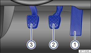 Fig. 137 Pedals in vehicles with manual transmission: ① Accelerator pedal, ② Brake pedal, ③ Clutch pedal.
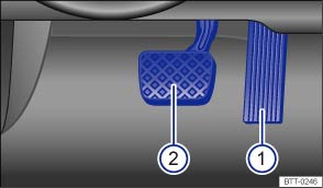 Fig. 138 Pedals in vehicles with automatic transmission: ① Accelerator pedal, ② Brake pedal.Read and follow the introductory information and safety information first⇒Introduction to the subject
All pedals must always be able to move freely in and out without interference from floor mats or other things.
Only use floor mats that leave the pedal area free and are held securely in place with floor mat fasteners to help prevent sliding.
If a brake circuit malfunctions, more brake pedal travel is needed to bring the vehicle to a full stop, and it is important that nothing is in the way when you have to depress the brake pedal harder and farther than normal.
WarningObjects in the driver footwell can prevent the pedals from moving freely. This can cause loss of vehicle control and increase the risk of serious personal injuries.
NoteAlways make sure that the pedals are able to move freely and that nothing can interfere with them. If a brake circuit fails, more brake pedal travel will be needed to bring the vehicle to a stop. The brake pedal must be pressed farther and harder than normal.
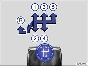 Fig. 139 Gearshift pattern of a 5-speed manual transmission.
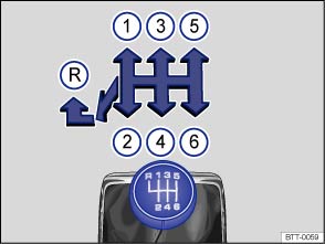 Fig. 140 Gearshift pattern of a 6-speed manual transmission.Read and follow the introductory information and safety information first⇒Introduction to the subject
The positions of the individual gears are shown on the gearshift lever ⇒ Fig. 139 or ⇒ Fig. 140 .
.The clutch pedal must be fully depressed to start the engine.
.You should always downshift gear by gear when driving, meaning always into the next lowest gear. Do not downshift when the engine rpm (revolutions per minute) is too high ⇒ . At fast speeds or high engine rpm, skipping over one or more gears when downshifting can cause damage to the clutch and transmission, even if a gear is not engaged ⇒ .
WarningDownshifting to a lower gear incorrectly can result in loss of vehicle control and can cause accidents and serious personal injuries.WarningWhen the engine is running and a gear is engaged, the vehicle will start to move as soon as the clutch pedal is released. This also applies when the parking brake is engaged.
NoteShifting down to a gear that is too low when driving at fast speeds or high engine rpm can cause extensive damage to the clutch and transmission. That is true even if the clutch pedal is pressed so that the clutch is not engaged.NoteTo help prevent damage and premature wear:
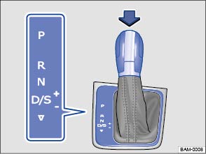 Fig. 141 Automatic transmission selector lever with shift lever release button (arrow).Read and follow the introductory information and safety information first⇒Introduction to the subject
Automatic transmission vehicles have an Automatic Shift Lock (ASL). With ASL, you must switch on the ignition, depress the brake pedal and hold it down while pressing the release button on the selector lever handle in the direction of the arrow ⇒ Fig. 141 to move the selector lever out of Park (P) and into a drive gear. When the selector lever is in Neutral (N), you also have to depress the brake pedal before you can move the selector lever to position (D/S), or Reverse (R).
If the ignition is switched on, either the current selector lever setting or the current gear is shown in the instrument cluster display.
| Selector lever position | Designation |
Meaning ⇒
|
|---|---|---|
|
|
Park |
The drive wheels are mechanically locked. Select only when the vehicle is not moving. To change the selector lever position, switch on the ignition (if it is off) and then press the selector lever release button while holding down the brake pedal. |
|
|
Reverse |
The Reverse gear is engaged. Shift into Reverse only when the vehicle is not moving. |
|
|
Neutral | Transmission is in Neutral position. No power is transmitted to the wheels and no engine braking is available. |
|
|
Drive (standard driving position) OR Sport drive (sport driving position) |
Standard driving position D: All forward gears shift up and down automatically. The transmission shifts as needed depending on engine load, individual driving style, and vehicle speed. |
|
Sport driving position S: All forward gears automatically upshift later and downshift earlier than in position D to take full advantage of the engine's power reserves. The transmission shifts as needed depending on engine load, individual driving style, and vehicle speed. The system will not, however, switch to the highest forward gear. |
||
| The timing of the gear shift is determined by the engine load, your individual driving style, and the vehicle speed. | ||
|
|
Changing gear selection | Switch between Drive (D) and Sport drive (S) by pulling the selector lever once to the rear from gear position D/S⇒ Fig. 141 . The selector lever always returns to gear position D/S. |
| It is possible to access Tiptronic selection from gear position D/S when either Drive (D) or Sport drive (S) is active ⇒ Shifting with Tiptronic . |
The Automatic Shift Lock (ASL) in Park (P) and Neutral (N) prevents drive positions from being engaged inadvertently, which would cause the vehicle to move.
To release the ASL, depress and hold the brake pedal with the ignition switched on. Press the release button on the selector lever at the same time.
The ASL is not engaged if the selector lever is moved quickly through Neutral (N) (e.g., when shifting from Reverse (R) to Drive (D/S)). This makes it possible to rock the vehicle backwards and forwards if it is stuck in snow or mud. The ASL engages automatically if the brake pedal is not depressed and the lever is in Neutral (N) for more than about 1 second and the vehicle is traveling no faster than about 3 mph (5 km/h).
In rare cases, the ASL may not engage on vehicles with a DSG automated transmission. If this happens, power to the drive wheels will be interrupted to prevent the vehicle from moving unexpectedly. The green indicator light will blink and a text message will be displayed. To engage the Automatic Shift Lock (ASL):
WarningMoving the selector lever to the wrong position can cause loss of vehicle control, a collision, and serious personal injury.
WarningUnintended vehicle movement can cause serious personal injury.
NoteEven though the transmission is in Park (P), the vehicle may move a couple of inches (a few centimeters) forwards or backwards if you take your foot off the brake pedal after stopping the vehicle without first setting the parking brake.If the selector lever is moved into Neutral (N) by mistake when the vehicle is moving, take your foot off the accelerator pedal. Wait until the engine speed has dropped to idle speed before moving the selector lever into a drive gear.Leaving the selector lever for a long period of time in any position other than Park (P) when the ignition is switched off can drain the vehicle battery.
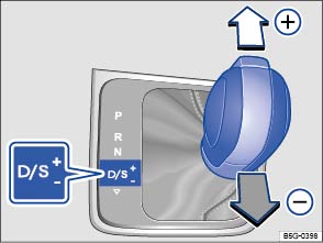 Fig. 142 Selector lever in Tiptronic position.
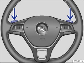 Fig. 143 Steering wheel with Tiptronic shift paddles (if equipped).Read and follow the introductory information and safety information first⇒Introduction to the subject
Tiptronic lets you upshift and downshift manually with the automatic transmission. When Tiptronic mode is used, the transmission stays in the current gear and does not upshift or downshift automatically unless the transmission senses a situation where upshifting or downshifting is necessary to keep the engine from over- or under-revving.
.Tiptronic will switch off automatically if the shift paddles have not been used for a while and the selector lever is not in the Tiptronic position.
Note
Read and follow the introductory information and safety information first⇒Introduction to the subject
All forward gears shift up and down automatically.
The steeper the grade, the lower the gear that must be selected. Lower gears increase the braking effect of the engine. Never coast downhill in Neutral (N).
If you stop and start up again when going uphill, you should use the Hill Start Assist feature ⇒ Starting assistance systems as long as the engine is running.
Vehicles without Hill Start Assist: If you stop on a hill with the vehicle in gear, you must depress the brake pedal or engage the parking brake to keep the vehicle from rolling. Do not release the brake pedal or the parking brake until the vehicle has started to move forward ⇒ .
The kick-down feature permits maximum acceleration when the selector lever is in the Drive or Sport Drive (D/S) position or in Tiptronic mode.
If you push the accelerator all the way down, the vehicle will automatically downshift, depending on vehicle speed and engine speed (rpm). This feature lets you take advantage of the full acceleration capacity of the vehicle ⇒ .
With kick-down activated, the transmission will stay in the current gear longer and not upshift until the engine reaches maximum rpm.
The launch control program lets you take advantage of maximum acceleration from a standstill.
. The vehicle will accelerate from a stop at the maximum rate.WarningRapid acceleration can cause skidding and loss of traction, especially on slippery roads, resulting in a loss of vehicle control, collisions, and serious personal injury.
Note
Read and follow the introductory information and safety information first⇒Introduction to the subject
If all selector lever position indicators in the instrument cluster display are highlighted against a bright background, there is a system malfunction. The automatic transmission or the DSG automated transmission will then operate in the emergency shift program. The emergency shift program lets you drive the vehicle, but at a reduced speed and without being able to use all of the forward gears.
In some cases, vehicles with a DSG automated transmission may not be able to shift into reverse. It is then impossible to drive the vehicle backwards.
In any event, have the automatic transmission checked by an authorized Volkswagen dealer or authorized Volkswagen Service Facility.
The DSG transmission may overheat, for example, due to frequent starts, extended creeping, or stop-and-go traffic. Overheating is indicated by the warning light and, if applicable, by a text message in the instrument cluster. An additional warning chime may sound. Stop and let the transmission cool down ⇒
.
If the vehicle does not move in the desired direction, the system may not have engaged the drive position correctly. Press the brake pedal and select the drive position again.
If the vehicle still does not move in the desired direction, there is a system malfunction. See your authorized Volkswagen dealer or authorized Volkswagen Service Facility for assistance to have the system checked.
Note
 Fig. 144 In the instrument cluster display: Gear recommendation.Read and follow the introductory information and safety information first⇒Introduction to the subject
Your vehicle may be equipped with a gear recommendation feature. The gear recommendation displays a gear in the instrument cluster display that can help reduce fuel consumption.
For vehicles with an automatic transmission: The selector lever must be in the Tiptronic position ⇒ Shifting with Tiptronic .
Key to ⇒ Fig. 144 :
Current gear.Recommended gear.If the optimal gear is already selected, another gear is not recommended . Only the current gear is displayed.
WarningThe gear recommendation is only intended to assist the driver to select a gear for optimum fuel economy. The gear recommendation cannot take road and traffic conditions into account.
Selecting the optimal gear helps to reduce fuel consumption.The gear recommendation display turns off if you depress the clutch pedal (manual transmission) or move the selector lever out of the Tiptronic position (automatic transmission).
Introduction to the subjectIn this chapter you will find information on the following subjects:⇒ Warning and indicator lights ⇒ Steering system information
Your vehicle is equipped with an electromechanical power steering system. The power steering works only when the engine is running.
The electromechanical power steering system automatically adjusts to driving speed, steering torque, and the steering angle of the wheels. It delivers extra steering force only when you are actually turning the wheels.
In vehicles with Driving Mode Selection, the selected driving mode can affect the steering behavior ⇒ Driving Mode Selection .
WarningTurning the steering wheel is very hard when the power steering system is not working. This makes it harder to steer and control the vehicle.
Read and follow the introductory information and safety information first⇒Introduction to the subject
| Lights up | Possible cause | Proper response |
|---|---|---|
|
|
Power steering malfunction. |
Have the power steering system checked immediately by an authorized Volkswagen dealer or an authorized Volkswagen Service Facility. |
|
|
Power steering assist is reduced. |
Stop, restart the engine, and drive a short distance. If the yellow warning light does not come on again, you do not need to have the steering system checked. Otherwise, have the steering checked immediately by an authorized Volkswagen dealer or an authorized Volkswagen Service Facility. |
| Vehicle battery was disconnected and has been reconnected. | Drive a short distance at about 10–12 mph (15–20 km/h). |
| Flashes | Possible cause | Proper response |
|---|---|---|
|
|
Electronic steering column lock malfunction. |
The ignition cannot be switched on. The vehicle must not be towed! Get professional assistance. |
|
|
Steering system stiff. | Turn the steering wheel back and forth. |
| Steering column not locked/unlocked. |
Switch the ignition off and then switch it on again. Heed any messages shown in the instrument cluster display, if applicable. On vehicles with Keyless Access ⇒ Starting the engine , press the starter button briefly twice in a row without depressing the brake or clutch pedal. Do not drive any farther if the steering column remains locked after you switch on the ignition. Contact your authorized Volkswagen dealer or an authorized Volkswagen Service Facility for assistance. |
When the ignition is switched on, several warning and indicator lights come on briefly for a function check. They go out after a few seconds.
WarningFailure to heed warning lights and instrument cluster text messages can cause the vehicle to break down in traffic and result in a collision and serious personal injury.
NoteFailure to heed warning lights or text WARNINGS can result in vehicle damage.
Read and follow the introductory information and safety information first⇒Introduction to the subject
To help prevent vehicle theft, you should always make sure the steering column is locked before leaving the vehicle.
Vehicles with Keyless Access: The steering column is locked if the driver door is opened with the ignition switched off. The vehicle must be standing still and the transmission must be in Park (P) on an automatic transmission vehicle.
If the driver door is opened before the ignition is switched off, the electronic steering column lock is activated only after the vehicle has been locked with the vehicle key or via the sensor in the door handle.
Vehicles without Keyless Access: The steering column is locked if the vehicle is stationary and the vehicle key is removed from the ignition switch.
| Engaging the steering column lock | Disengaging the steering column lock |
|---|---|
| Park the vehicle ⇒ Braking and parking . | Turn the steering wheel slightly to take pressure off the steering column lock. |
| Remove the vehicle key. | Insert the vehicle key into the ignition switch. |
| Turn the steering wheel slightly until you hear the steering column lock engage. | Hold the steering wheel in this position and turn the ignition switch. |
Power steering automatically adjusts to driving speed, steering torque, and the steering angle of the wheels. Power steering works only when the engine is running.
If power steering is reduced or lost completely, it will be much harder to steer and control the vehicle.
Counter-steering assistance is part of Electronic Stability Control (ESC). This feature makes it easier for the driver to control the vehicle in difficult situations. For example, if you have to brake hard on a surface that provides uneven traction, the vehicle could pull to the right or left. ESC detects this situation and helps the driver counter-steer with additional steering power ⇒ .
Your vehicle may be equipped with progressive steering, which can adjust the force of the steering movement in a driving situation. Progressive steering only works when the engine is running.
In city traffic, less steering input is required when parking, maneuvering, or turning sharply.
When driving on country roads or highways, the progressive steering provides a more sporty, direct steering response and a more dynamic feel.
WarningThe counter-steering assistance in ESC can do no more than help the driver steer in difficult situations. The driver must still control the vehicle. The vehicle does not steer by itself with this feature!NoteIf the ignition is off, the steering column lock will engage and the vehicle cannot be steered. For this reason, you must leave the ignition on when going through an automatic car wash, for example, so that the wheels will still steer.
Introduction to the subjectIn this chapter you will find information on the following subjects:⇒ Warning and indicator lights ⇒ Parking brake (Golf, Golf GTI) ⇒ Electronic parking brake (Golf R) ⇒ Parking ⇒ About the brakes ⇒ Braking assistance systems ⇒ Switching Anti-Slip Regulation (ASR) and ESC Sport mode on and off ⇒ Brake fluid
The braking assistance systems are the Anti-Lock Brake System (ABS), Brake Assist System (BAS), Electronic Differential Lock (EDL), Anti-Slip Regulation (ASR), and Electronic Stability Control (ESC).
WarningDriving with bad brakes or worn brake pads can cause a collision and serious personal injury.
WarningParking improperly can cause serious personal injury.
Note
Read and follow the introductory information and safety information first⇒Introduction to the subject
| Lights up |
Possible cause or meaning ⇒
|
Proper response |
|---|---|---|
|
|
Parking brake engaged. |
Release the parking brake ⇒ Parking brake (Golf, Golf GTI) . |
|
|
Brake system malfunction. |
Get professional assistance immediately ⇒ Brake system malfunction . |
| Brake fluid level too low. |
Check the brake fluid level ⇒ Brake fluid level . |
|
|
Together with the ABS indicator light |
See an authorized Volkswagen dealer or an authorized Volkswagen Service Facility. The vehicle brakes will work without ABS. |
|
|
|
ESC switched off by the system. | Switch ignition off and on again. You may have to drive a short distance. |
| ESC malfunction. | See an authorized Volkswagen dealer or an authorized Volkswagen Service Facility. | |
|
Together with the ABS indicator light |
See an authorized Volkswagen dealer or an authorized Volkswagen Service Facility. The vehicle brakes will work without ABS. |
|
| Vehicle battery has been reconnected. | Drive a short distance at a speed of 10–12 mph (15–20 km/h). If the indicator light stays on, see an authorized Volkswagen dealer or an authorized Volkswagen Service Facility ⇒ Vehicle battery . | |
|
|
ASR manually deactivated. | Switch on ASR or switch off ESC Sport mode ⇒ Switching Anti-Slip Regulation (ASR) and ESC Sport mode on and off . ASR automatically turns on when you turn the ignition off and back on again. |
| OR: ESC Sport mode manually activated. | ||
|
|
Together with the ESC indicator light |
See an authorized Volkswagen dealer or an authorized Volkswagen Service Facility. The vehicle brakes will work without ABS. |
|
Together with warning light |
||
|
|
Electronic parking brake malfunction (if equipped). | See an authorized Volkswagen dealer or an authorized Volkswagen Service Facility. |
|
|
Brake pedal not depressed. | Depress the brake pedal to select a gear or drive position. |
| Flashes |
Possible cause or meaning ⇒
|
Proper response |
|---|---|---|
|
|
ESC or ASR is operating. | Take foot off accelerator pedal. Adapt driving to road conditions. |
|
|
The release button in the selector lever is not engaged. | Engage the Automatic Shift Lock (ASL) ⇒ Automatic transmission: Selector lever . |
When the ignition is switched on, several warning and indicator lights come on briefly for a function check. They go out after a few seconds.
WarningFailure to heed warning lights and instrument cluster text messages can cause the vehicle to break down in traffic and result in a collision and serious personal injury.
WarningDriving with bad brakes can cause a collision and serious personal injury.
NoteFailure to heed warning lights or text WARNINGS can result in vehicle damage.
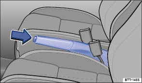 Fig. 145 Between the front seats: Parking brake.Read and follow the introductory information and safety information first⇒Introduction to the subject
The following information applies to models with a parking brake lever. If your vehicle is equipped with an electronic parking brake, see ⇒ Electronic parking brake (Golf R) .
WarningImproper use of the parking brake can cause accidents and severe injuries.
NoteEven though the transmission is in Park (P), the vehicle may move a couple of inches (a few centimeters) forwards or backwards if you take your foot off the brake pedal after stopping the vehicle without first firmly setting the parking brake.A warning signal sounds if you drive faster than about 4 mph (6 km/h) with the parking brake engaged.
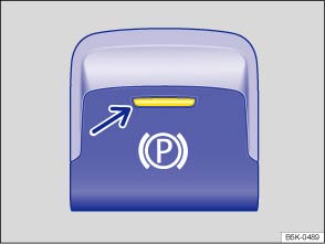 Fig. 146 In the lower center console: Electronic parking brake switch.Read and follow the introductory information and safety information first⇒Introduction to the subject
The following information applies to models with an electronic parking brake. If your vehicle is equipped with a parking brake lever, see ⇒ Parking brake (Golf, Golf GTI) .
You can engage the electronic parking brake any time the vehicle is not moving - even if the ignition is switched off. Always engage the parking brake when you leave or park the vehicle.
The electronic parking brake releases automatically when you start driving if the driver door is closed. With a manual transmission, you must also press the clutch pedal all the way down before you start driving so the system recognizes that the parking brake should be switched off.
You can prevent the electronic parking brake from switching off automatically by pulling and holding the switch while pulling away.
The electronic parking brake is only switched off after you let go of the switch. This makes it easier to start off with a heavier load.
In vehicles with an automatic transmission, the electronic parking brake automatically switches on to prevent the vehicle from moving when all of the following conditions are met:
Only use the emergency braking function in an emergency, when you cannot stop the vehicle using the brake pedal ⇒ !
WarningImproper use of the electronic parking brake can cause accidents and severe injuries.
NoteEven though the transmission is in Park (P), the vehicle may move a couple of inches (a few centimeters) forwards or backwards if you take your foot off the brake pedal after stopping the vehicle without first firmly setting the parking brake.Vehicles with manual transmission: The electronic parking brake switches off automatically when you release the clutch pedal and press the accelerator pedal at the same time.If the vehicle battery is dead, the electronic parking brake cannot be released. Use a jump-start ⇒ Jump-starting .You may hear noises when setting or releasing the electronic parking brake.If the electronic parking brake is not used for a while, an automatic system check will occasionally run when the vehicle is parked. This system check makes audible noises.
Read and follow the introductory information and safety information first⇒Introduction to the subject
Please note legal regulations when stopping and parking your vehicle.
Please perform these steps only in the order listed.
.Before stopping the engine, turn the steering wheel so that, if the vehicle starts to roll, its front wheels will roll into the curb:
WarningThe vehicle exhaust system and the catalytic converter or diesel particulate filter get very hot. They can cause fires and serious personal injury.
WarningLeaving the vehicle when the selector lever is not in Park (P) (automatic transmissions) can cause the vehicle to roll away. This can cause accidents and serious personal injuries.
Note
Read and follow the introductory information and safety information first⇒Introduction to the subject
New brake pads do not provide full performance during the first 100 to 200 miles (200 to 300 km) and must first be broken in ⇒ . To some extent, you can make up for the somewhat reduced performance by applying more pressure to the brake pedal. But, during the break-in period, the stopping distance for hard braking and emergency braking will be longer until the brakes are fully broken in. Avoid hard braking and situations that might require hard braking (such as following other vehicles too closely) – especially during the break-in period.
Brake pad wear depends mostly on operating conditions and the way the vehicle is driven. If you do a lot of city and short-distance driving and/or have a sporty driving style, you should have the brake pads checked by an authorized Volkswagen dealer or authorized Volkswagen Service Facility more often than the regular service intervals.
Wet brakes (for example, after driving through water or washing the vehicle or after heavy rainfall) will not brake as well. Stopping distances will be longer when brake discs are wet or, in winter, even icy. Wet or icy brakes must be dried as soon as possible by carefully applying the brakes a couple of times while traveling at a relatively high speed. Make sure nobody is behind you and that you do not endanger yourself or others ⇒ .
Brakes coated with road salt also react slower and need longer stopping distances. If there is salt on the roads and you are not braking regularly, brake carefully and gently from time to time to remove any salt coating from the brake discs and pads ⇒ .
Brake disc corrosion (rust) and dirt buildup on the brake pads are more likely to occur if the vehicle is not driven much or is driven only for short distances with little braking. If the brakes have not been used and there is some rust on the discs, clean the brake discs and pads once in a while by carefully braking a couple of times while driving at relatively high speed to help clean the brake discs and pads. Make sure nobody is behind you and that you do not endanger yourself or others ⇒ .
If you brake and find that the vehicle doesn't brake nearly as well as it used to (sudden increase in stopping distance), a brake circuit may have failed. The brake warning light or
will light up and a message may appear in the instrument cluster display. If you believe the vehicle is safe to drive, immediately take it to the nearest authorized Volkswagen dealer or authorized Volkswagen Service Facility for repair. Drive slowly and very carefully, allow for the longer stopping distance, and be ready to push longer and harder on the brake pedal to slow the vehicle down.
The brake booster works only when the engine is running. It increases the force on the brakes above and beyond the pressure put on the brake pedal by the driver.
If the brake booster is not working, or if the vehicle has to be towed, you will have to push the brake pedal harder to make up for the lack of booster assistance and the resulting longer stopping distance ⇒ .
WarningNew brake pads do not provide maximum braking performance.
WarningOverheated brakes will reduce the vehicle's stopping power and increase stopping distances considerably.
WarningWet brakes or brakes coated with ice or road salt react slower and need longer stopping distances.
WarningDriving when the brake booster is not working increases stopping distances and can cause accidents and serious personal injuries.
Note
When the front brakes are serviced, you should have the rear brake pads inspected at the same time. The wear of all brake pads should be visually checked regularly. The best way to check for brake pad wear is to have your authorized Volkswagen dealer or authorized Volkswagen Service Facility visually inspect the pads through the openings in the wheel rims or from underneath the vehicle. If necessary, the wheels can be taken off for a more thorough inspection.
Read and follow the introductory information and safety information first⇒Introduction to the subject
The ESC, ABS, BAS, ASR, and EDL braking assistance systems work only when the engine is running. These systems can significantly improve active driving safety.
ESC helps to improve road holding and vehicle dynamics to help reduce the probability of skidding and loss of vehicle control. It works only when the engine is running. ESC detects certain difficult driving situations, including when the vehicle is beginning to spin (yaw) out of control. ESC then helps you to get the vehicle back under control by selectively braking the wheels and/or reducing engine power and by providing steering assistance to help hold the vehicle on the driver's intended course.
ESC has limitations. It is important to remember that ESC cannot overcome the laws of physics. It will not always be able to help out under all conditions you may come up against. For example, ESC may not always be able to help you master situations where there is a sudden change in the coefficient of friction of the road surface. When there is a section of dry road that is suddenly covered with water, slush or snow, ESC cannot perform the same way it would on a dry surface. If the vehicle hydroplanes (rides on a cushion of water instead of the road surface), ESC will not be able to help you steer the vehicle because contact with the pavement has been interrupted and the vehicle cannot be braked or steered. During fast cornering, particularly on winding roads, ESC cannot always deal as effectively with difficult driving situations as it can at lower speeds. When towing a trailer, ESC is not able to help you regain control as it would if you were not towing a trailer.
Always adjust your speed and driving style to visibility, road, traffic, and weather conditions. ESC cannot override the vehicle's physical limits, increase the available traction, or keep a vehicle on the road if road departure is a result of driver inattention. Instead, ESC improves the possibility of keeping the vehicle under control and on the road during extreme maneuvers by using the driver's steering inputs to help keep the vehicle going in the intended direction. If you are traveling at a speed that causes you to run off the road before ESC can provide any assistance, you may not experience the benefits of ESC.
ESC includes and/or works together with the ABS, BAS, ASR, EDL, and XDL systems (see below). ESC is switched on all the time. In certain situations when you need less traction or additional traction cannot be achieved, you can switch off ASR by pressing the button ⇒ Fig. 147 .
On appropriately equipped vehicles, you can also switch off ASR in the Infotainment system by pressing the button followed by the
and ESC System function keys ⇒ Menu and system settings .
ESC Sport mode can also be switched on ⇒ Switching Anti-Slip Regulation (ASR) and ESC Sport mode on and off .
Be sure to switch ASR on again when you no longer need less traction.
In the event of an accident, the Automatic Post-Collision Braking System can help the driver to reduce the risk of skidding and the danger of secondary collisions through automatic braking.
The Automatic Post-Collision Braking System only functions in frontal, side, and rear collisions if the airbag control unit registers the corresponding triggering threshold during the accident, and the accident occurs at a speed greater than 6 mph (10 km/h).
The ESC brakes the vehicle automatically, provided that the hydraulic braking system, the ESC, and the electrical system are undamaged in the accident and remain functional.
The following actions override automatic braking in the event of an accident:
ABS helps to keep the wheels from locking up and helps to maintain the driver's ability to steer and control the vehicle. This means the vehicle is less likely to skid, even during hard braking:
When ABS is doing its job, you will notice a slight vibration through the brake pedal and hear a noise. ABS cannot shorten the stopping distance under all conditions. The stopping distance may even be longer, for instance, when driving on gravel or on newly fallen snow covering an icy or slippery surface.
The Brake Assist System can help to reduce stopping distances. If you press the brake pedal very quickly, BAS detects an emergency situation. It then very quickly builds up full brake system pressure, maximizing braking power and reducing the stopping distance. This way, ABS can be activated more quickly and efficiently.
Do not reduce pressure on the brake pedal! BAS switches off automatically as soon as you release or let up on the brake.
ASR reduces engine power directed to spinning wheels and adjusts power to the road conditions. Even under poor road conditions, ASR can make it easier to get moving, accelerate, and climb hills.
ASR can be switched on and off manually ⇒ Switching Anti-Slip Regulation (ASR) and ESC Sport mode on and off .
EDL is applied during regular straight-line acceleration. EDL gently brakes a drive wheel that has lost traction (spinning) and redirects the drive force to other drive wheels. In extreme cases, EDL automatically switches off to keep the brake from overheating. As soon as the brake has cooled down, EDL automatically switches on again.
XDL is an extension of the Electronic Differential Lock system. XDL does not react to drive wheel slippage when driving straight ahead. Instead, XDL detects slippage of the inside front wheel during fast cornering. XDL applies enough brake pressure to this wheel in order to stop the slippage. This improves traction, which helps the vehicle stay on track.
WarningDriving fast on icy, slippery, or wet roads can lead to a loss of control and result in serious personal injury for you and your passengers.
WarningThe effectiveness of ESC can be significantly reduced if other components and systems that affect vehicle dynamics, including but not limited to brakes, tires, and other systems mentioned above, are not properly maintained or functioning.
All 4 wheels must be equipped with identical tires in order for ESC and ASR to work properly. Differences in the tread circumference of the tires can cause the system to reduce the engine power when it is not expected.If ABS is not working, ESC, ASR, and EDL will also not work.You may hear noises when these systems are active.
 Fig. 147 In the center console: Button for switching ASR or ESC Sport mode on and off manually (if equipped).Read and follow the introductory information and safety information first⇒Introduction to the subject
The Electronic Stability Control (ESC) only works when the engine is running. This system includes ABS, EDL and ASR.
When ASR is switched off, the indicator light in the instrument cluster lights up ⇒ Warning and indicator lights . Switch off ASR only in situations where there is not enough traction, such as the following:
Afterward, activate ASR again.
When ASR is switched off, the indicator light in the instrument cluster lights up ⇒ Warning and indicator lights .
Depending on the vehicle model, when switching off the ASR, the ESC can also be switched off or the ESC sport mode (ESC Sport) can be switched on. ESC Sport can also be switched on in addition to switching off the ASR.
The brake intervention functions of ESC are limited when ESC Sport is switched on. It can be switched on and off by pressing the button ⇒ Fig. 147 .
|
Button |
Golf GTI | Golf R |
|---|---|---|
| Press for about 1 second | ASR switched off | ASR switched off, ESC Sport switched on |
| Press and hold longer than 3 seconds | ASR switched off, ESC Sport switched on | ASR and ESC switched off |
| Press again | ASR (with ESC) switched on | ASR (with ESC) switched on |
Depending on vehicle equipment, additional text messages may appear in the instrument cluster display to provide further information or to ask you to perform certain tasks ⇒ Instrument cluster .
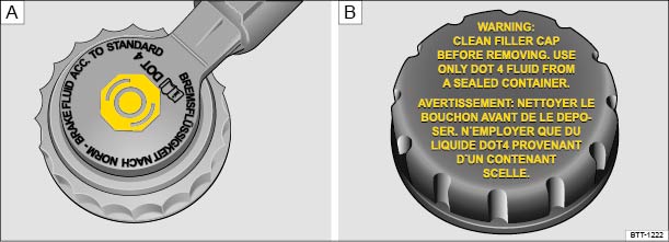 Fig. 148 In the engine compartment: Brake fluid reservoir cap (cap design may vary depending on vehicle equipment).Read and follow the introductory information and safety information first⇒Introduction to the subject
Brake fluid absorbs water from the air over time. Too much water in the brake fluid will damage the brake system. Water also lowers the boiling point of the brake fluid. Too much water in the brake fluid can cause vapor lock during heavy brake use or hard braking. Vapor lock reduces braking performance, increases stopping distances and can even cause total brake failure. Your safety and the safety of others depends on brakes that are working properly at all times ⇒ .
Volkswagen has developed a special brake fluid that is optimized for the brake system in your Volkswagen. Volkswagen recommends that you use brake fluid that expressly conforms to quality standard VW Standard 501 14 for optimum performance of the brake system. Check the information on the container for the brake fluid you want to use to make sure it meets the requirements for your vehicle.
Brake fluid that complies with VW Standard 501 14 can be purchased from your authorized Volkswagen dealer or authorized Volkswagen Service Facility.
If this special brake fluid is not available you may – under these circumstances – use another high quality brake fluid that complies with U.S. Federal Motor Vehicle Safety Standard (FMVSS) 116 DOT 4 ⇒ .
Please note, however, that not all brake fluids that comply with U.S. Federal Motor Vehicle Safety Standard (FMVSS) 116 DOT 4 have the same chemical composition. Some of these brake fluids can contain chemicals that could, over time, degrade or damage internal parts of the vehicle’s brake system.
Volkswagen therefore recommends that you use brake fluid that expressly complies with VW Standard 501 14 for optimum brake system performance over the long term.
The fluid level in the transparent brake fluid reservoir must always be between the MIN and MAX marking ⇒ .
On some vehicles, engine components may partially block the view of the brake fluid reservoir and make it impossible to see the brake fluid level. If you cannot clearly see the brake fluid level in the brake fluid reservoir, please see an authorized Volkswagen dealer or authorized Volkswagen Service Facility.
The brake fluid level drops slightly when the vehicle is being used as the brake pads wear and the brakes are automatically adjusted.
Brake fluid must be changed according to the service schedule in your ⇒BookletWarranty and Maintenance,. Have the brake fluid checked by an authorized Volkswagen dealer or an authorized Volkswagen Service Facility. Refill only with new brake fluid that meets the standards listed above.
WarningBrake failure and reduced brake performance can be caused by not having enough brake fluid in the reservoir or by old or incorrect brake fluid.
WarningBrake fluid is poisonous.
NoteBrake fluid will damage vehicle paint, plastic parts, and tires. Wipe any brake fluid off vehicle paint and other vehicle parts immediately.Brake fluid can pollute the environment. Brake fluid that has leaked out must be collected and disposed of properly, following all applicable environmental regulations.
Introduction to the subjectIn this chapter you will find information on the following subjects:⇒ Efficient driving style ⇒ Fuel-efficient driving ⇒ Think Blue. Trainer.
Fuel consumption, environmental impact, and wear and tear on engine, brakes and tires depend mainly on the following 3 factors:
You can reduce fuel consumption by up to 25% by using a few simple techniques and adjusting your driving style.
WarningAlways adjust your speed and the distance you keep between you and the vehicles ahead of you to the road, traffic, weather, and visibility conditions.
Read and follow the introductory information and safety information first⇒Introduction to the subject
As a rule, the following applies: The higher gear is always the most efficient gear. The rule of thumb for most vehicles is to drive in 3rd gear at 20 mph (30 km/h), 4th gear at 25 mph (40 km/h), 5th gear at 30 mph (50 km/h), and 6th gear at 36 mph (60 km/h).
If traffic and driving conditions permit, skipping gears when upshifting also saves fuel.
Do not run the gears up to their limit. Use 1st gear only to start moving and then smoothly shift into 2nd gear. Avoid kick-downs in vehicles with automatic transmissions.
If you take your foot off the accelerator, fuel delivery to the engine is interrupted, which lowers fuel consumption.
Therefore, when nearing a red stop light, for instance, allow the vehicle to coast without using the accelerator. Press the clutch pedal and release it only if the vehicle moving too slowly or the coasting distance is too long. The engine will then continue to run at idle.
In situations where the vehicle will be stopped for a longer period of time, such as at a railroad crossing, physically switch off the engine.
Frequent braking and acceleration increase fuel consumption significantly. If you keep a sufficiently large distance away from the car in front of you, you can maintain a more constant speed. Active braking and accelerating is then not necessarily required.
Consistency is more important than speed. The more smoothly you drive, the less fuel the vehicle consumes.
When driving on the highway or freeway, a constant, moderate speed is more efficient and economical than constantly accelerating and braking. Usually you can reach your destination just as quickly by driving at a moderate, but steady speed.
The cruise control can assist in maintaining a uniform driving style.
Comfort inside the vehicle is nice and important, but it is important to use extra electrical loads in an environmentally conscious manner.
Some devices can increase fuel consumption when activated (examples):
NoteNever let the vehicle coast or roll down a hill in Neutral (N), especially when the engine is not running. The transmission will not be lubricated and will be damaged.
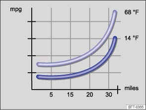 Fig. 149 Fuel consumption in miles per gallon (mpg) at 2 different outside air temperatures.
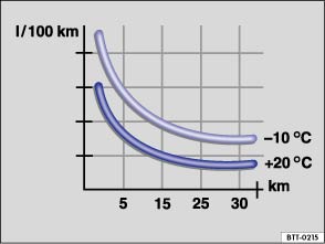 Fig. 150 Fuel consumption in l/100 km at 2 different outside air temperatures.Read and follow the introductory information and safety information first⇒Introduction to the subject
Driving defensively and economically can easily reduce fuel consumption by 10 to 15%.
The vehicle consumes the most fuel when accelerating. Defensive driving requires less braking and therefore less acceleration. If possible, coast the vehicle to a stop, for example, when you can see that the next traffic light is red or about to turn red.
A cold engine consumes significantly more fuel immediately after starting. It takes a few miles (km) before the engine is warmed up and fuel consumption is stabilized.
To reduce fuel consumption and the emission of pollutants effectively, the engine and catalytic converter must reach their optimal operating temperature. Critical in this context is also the outside air temperature.
⇒ Fig. 149 and ⇒ Fig. 150 display the varying fuel consumption rates for the same distance driven, once at +68 °F (+20 °C) and once at +14 °F (-10 °C).
Therefore, avoid driving short distances unnecessarily and consolidate routes.
Under the same conditions, the vehicle consumes more fuel in winter than in summer.
Letting the engine run to warm up is not only illegal in some places, but also technically not necessary and wastes fuel.
The proper tire pressure helps reduce rolling resistance as well as fuel consumption.
When purchasing new tires, always make sure that the tires are optimized for lower rolling resistance.
Fully synthetic, low viscosity engine oils that expressly comply with Volkswagen oil quality standards reduce fuel consumption. Low viscosity engine oils reduce the frictional resistance on the engine and are distributed more evenly and quickly, particularly when cold-starting the engine. The effect is particularly apparent in vehicles that frequently travel short distances.
Always ensure the right engine oil level is maintained and keep to the scheduled service intervals (engine oil changes).
Make sure the engine oil that you purchase expressly complies with Volkswagen oil quality standards and is the oil approved by Volkswagen for your vehicle.
The lighter the vehicle, the more economical and eco-friendly it will be. For example, an extra 220 lbs (100 kg) of weight increases fuel consumption by up to 1 pint per 60 miles (0.3 l/100 km).
Remove all unnecessary items and unnecessary dead weight from the vehicle.
The more aerodynamic the vehicle, the less fuel it will consume. Aftermarket components such as bicycle racks reduce its aerodynamic performance.
Therefore, remove unnecessary structures and unused rack systems, particularly if planning to drive at higher speeds.
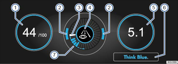 Fig. 151 Infotainment system screen: Think Blue. Trainer.Read and follow the introductory information and safety information first⇒Introduction to the subject
The Think Blue. Trainer. analyzes your driving while the vehicle is moving forward. It then generates a visual display which can help you to adopt a more fuel-efficient driving style.
| ⇒ Fig. 151 | Meaning |
|---|---|
| ① |
The Blue Score is a rating of your driving style efficiency on a scale of 0 to 100. The higher the value displayed, the more efficient your driving style. You can touch the display to show the statistics for the last 30 minutes of the current trip. If the current driving time is less than 30 minutes, the values from the last trip are displayed in grey. A blue frame around the display indicates a fuel-efficient and consistent driving style. A grey frame indicates a less efficient driving style. |
| ② | The position of the two arcs in the outer ring shows the acceleration. At a constant speed, the arcs appear in the central area. The arcs move up and down during braking and acceleration, respectively. |
| ③ | The white segment in the central ring shows the current evaluation status. It gradually moves clockwise about every 5 seconds, creating a blue segment each time. See ⑦. |
| ④ | Various symbols in the inner ring provide feedback about the current driving style: |
|
|
|
|
|
|
|
|
|
|
|
|
| ⑤ |
The average fuel consumption is displayed in the units set by the driver, for example, Av. mpg or Av. l/100km. The value refers to the distance traveled since the start of the trip. You can touch the display to show the statistics for the last 30 minutes of the current trip. If the current driving time is less than 30 minutes, the values from the last trip are displayed in grey. A blue frame around the display indicates a fuel-efficient and consistent driving style. A grey frame indicates a less efficient driving style. |
| ⑥ | Tap the Think Blue. function key for additional tips on saving fuel. |
| ⑦ | The blue segments in the central ring show driving style efficiency. Each segment indicates an elapsed time of about 5 seconds. The larger the blue segment, the more efficient the driving style during this period. |
When the vehicle is stationary, press the Infotainment button until the Think Blue. Trainer. ⇒ Fig. 151 is displayed ⇒ Infotainment system .
OR: When the vehicle is stationary, press the Infotainment button once, then tap the Selection function key and select Think Blue. Trainer..
WarningNever pay so much attention to the graphics shown on the screen that you fail to notice what is going on around you.
Introduction to the subjectIn this chapter you will find information on the following subjects:⇒ Indicator light ⇒ Hill Start Assist (Hill Hold) ⇒ Auto Hold (Golf R) WarningThe intelligent technology of the dynamic starting assistance features cannot overcome the laws of physics. Never let the increased convenience provided by the dynamic starting assistance features tempt you into taking risks.
WarningDriving with too little fuel in the fuel tank increases the risk of stalling, especially when driving up and down hills.
Read and follow the introductory information and safety information first⇒Introduction to the subject
| Lights up |
Possible cause or meaning ⇒
|
Proper response |
|---|---|---|
|
|
The vehicle is being held by the Auto Hold feature (if equipped). | Switch off the Auto Hold feature, if necessary ⇒ Auto Hold (Golf R) . |
When the ignition is switched on, several warning and indicator lights come on briefly for a function check. They go out after a few seconds.
WarningFailure to heed warning lights and instrument cluster text messages can cause the vehicle to break down in traffic and result in a collision and serious personal injury.
NoteFailure to heed warning lights or text WARNINGS can result in vehicle damage.
Read and follow the introductory information and safety information first⇒Introduction to the subject
Some vehicles are equipped with Hill Start Assist (Hill Hold), a feature that helps keep the vehicle from rolling backwards when starting out on a hill, for example after stopping at a traffic light. You don't have to apply and release the parking brake while depressing the accelerator. For Hill Start Assist to work, the engine must be running and the vehicle must be in First Gear or Reverse (manual transmission) or in Drive or Sport Drive (D/S) or Reverse (R) (automatic transmission) and you must use the foot brake to hold the vehicle before starting to move.
Hill Start Assist keeps the brake applied for almost 2 seconds with the same force you used to prevent the vehicle from moving. This gives you time to take your foot off the brake, let the clutch out on a manual transmission vehicle, and gently depress the accelerator to get the vehicle moving again. If you do not depress the accelerator pedal and get the vehicle moving again within this time, the brakes will release and the vehicle will roll downhill. Furthermore, if any requirement for engaging Hill Start Assist is no longer met while the vehicle is stopped, Hill Start Assist disengages and the brakes are automatically released and will no longer hold the vehicle.
| Step | Manual transmission | Automatic transmission |
|---|---|---|
| 1. | Hold the stopped vehicle on an incline with the foot or parking brake. | |
| 2. | The engine must be running smoothly. | |
| 3. | A manual transmission vehicle must be in 1st gear (1) if headed up a hill or in Reverse (R) if backing up a hill; you must hold the clutch down and the foot brake must be depressed to keep the vehicle from moving. | An automatic transmission vehicle must be in Reverse (R) or Drive or Sport Drive (D/S), and the foot brake must be depressed to keep the vehicle from moving. |
| 4. | To drive off, take your foot off the brake pedal as you let the clutch out and gently depress the accelerator within 2 seconds. If the accelerator is not depressed, the brakes will release automatically. | To drive off, take your foot off the brake pedal and gently depress the accelerator within 2 seconds. |
WarningThe intelligent technology of Hill Start Assist cannot overcome the laws of physics. Never let the increased convenience provided by Hill Start Assist tempt you into taking risks.
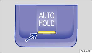 Fig. 152 In the lower center console: Button for Auto Hold (if equipped).Read and follow the introductory information and safety information first⇒Introduction to the subject
Depending on vehicle equipment, models equipped with an electronic parking brake may also be equipped with the Auto Hold feature.
The indicator light in the
button ⇒ Fig. 152 (arrow) lights up when the feature is switched on.
When switched on, the Auto Hold feature automatically prevents the vehicle from rolling away without the driver having to press the brake pedal.
The Auto Hold feature holds the vehicle as soon as it detects that the vehicle is not moving and the brake pedal is released. The green indicator light in the instrument cluster display lights up to show that the vehicle is being held by the electronic parking brake.
When the driver accelerates, the Auto Hold feature releases the electronic parking brake again. The green indicator light in the instrument cluster display goes out and the vehicle begins to move, depending on the incline.
Vehicles with automatic transmission: If the selector lever is moved to position N, Auto Hold will not switch on and will remain deactivated. The vehicle will not be held at a standstill ⇒ .
If any of the conditions for using Auto Hold change while the vehicle is not moving, the Auto Hold feature switches off automatically and the green indicator light in the instrument cluster display goes out, along with the yellow indicator light in the
button.
The electronic parking brake may engage automatically to hold the vehicle securely ⇒ . The red indicator light or
comes on in the instrument cluster display.
Press the
button ⇒
. The indicator light in the button ⇒ Fig. 152 (arrow) goes out when Auto Hold is switched off.
If Auto Hold is switched off while it is holding the vehicle in place, the electronic parking brake switches on automatically. The electronic parking brake will not switch on if the brake pedal is depressed when Auto Hold is switched off ⇒
If Auto Hold has been switched on using the
button before switching the ignition off, the Auto Hold feature switches on automatically when the ignition is switched on the next time. The same applies if the Auto Hold feature is switched off – it will remain switched off when the ignition is switched on again.
You can switch the Auto Hold feature off temporarily so that the vehicle can roll more easily, for example, when maneuvering.
Auto Hold switches on again as soon as the brake pedal is depressed and the vehicle comes to a standstill.
WarningThe intelligent technology of the Auto Hold feature cannot overcome the laws of physics. Never let the increased convenience provided by the Auto Hold feature tempt you into taking risks.
NoteBefore entering a car wash, always deactivate Auto Hold. Otherwise, the electronic parking brake can engage automatically and cause damage.
Introduction to the subjectIn this chapter you will find information on the following subjects:⇒ Indicator lights ⇒ Cruise control operation
Your vehicle may be equipped with cruise control, which helps maintain an individually stored constant speed when driving above about 15 mph (20 km/h).
Cruise control slows down the vehicle only by reducing the flow of fuel to the engine, not by braking ⇒ .
WarningUsing the cruise control when it is not possible to drive safely at a constant speed can be dangerous and can lead to an accident and serious personal injuries.
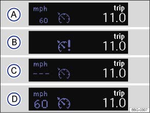 Fig. 153 In the instrument cluster display: Cruise control status indications.Read and follow the introductory information and safety information first⇒Introduction to the subject
Different cruise control versions are available. The stored speed is shown in the instrument cluster display on some equipment versions.
Status⇒ Fig. 153
Cruise control temporarily deactivated. Stored speed displayed in a darker shade or in smaller numbers.System malfunction. See an authorized Volkswagen dealer or an authorized Volkswagen Service Facility.Cruise control activated. No speed stored in memory.Cruise control is active. Stored speed displayed in white or in larger numbers.| Lights up | Possible cause |
|---|---|
|
|
Cruise control is regulating the vehicle speed. |
When the ignition is switched on, several warning and indicator lights come on briefly for a function check. They go out after a few seconds.
WarningFailure to heed warning lights and instrument cluster text messages can cause the vehicle to break down in traffic and result in a collision and serious personal injury.
NoteFailure to heed warning lights or text WARNINGS can result in vehicle damage.If the cruise control is switched on when the ignition is switched off, it may be switched on automatically the next time the ignition is switched on, depending on vehicle equipment. No speed is stored for the cruise control.The displays may vary depending on vehicle equipment.
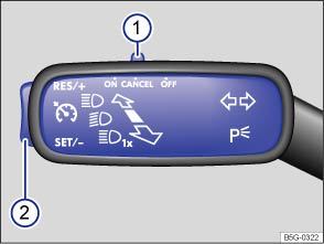 Fig. 154 On the turn signal lever: Cruise control buttons and switches (if equipped).
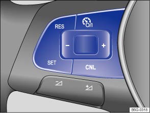 Fig. 155 Left-hand side of the multi-function steering wheel (if equipped): Buttons for operating the cruise control.Read and follow the introductory information and safety information first⇒Introduction to the subject
| In order to: | You must: ⇒ Fig. 154 or ⇒ Fig. 155 | Result: |
|---|---|---|
| Switch on cruise control. |
Move switch ① on the turn signal lever to the OR: Press the |
System is switched on, but does not regulate vehicle speed until a speed is set. |
| Set cruise control to current vehicle speed. |
Press button ② on the turn signal lever in the area marked OR: Press the |
Current vehicle speed is set; cruise control helps to maintain this speed. |
| Temporarily deactivate cruise control. |
Move switch ① on the turn signal lever to the OR: Press the OR:Briefly press the OR: Depress the brake pedal. |
Cruise control is temporarily deactivated. The speed is still stored in the memory. |
| Resume speed stored in cruise control. |
Press button ② on the turn signal lever in the area marked OR: Press the |
Cruise control resumes speed previously set. |
| Increase set speed (while cruise control is actively controlling vehicle speed). |
Press button ② on the turn signal lever in the area marked OR: Press the Press briefly to increase the speed by 1 mph (1 km/h) and store it. Press and hold to increase the stored speed continuously until you release the button. |
The vehicle will accelerate until the new higher speed is reached and saves the new higher speed in the memory. |
| Reduce set speed (while cruise control is actively controlling vehicle speed). |
Press button ② on the turn signal lever in the area marked OR: Press the Press briefly to reduce the speed by 1 mph (1 km/h) and store it. Press and hold to reduce the stored speed continuously until you release the button. |
Cruise control will slow the vehicle down without braking by reducing the flow of fuel to the engine until the new lower speed is reached and saves the new lower speed in the memory. |
| Switch off cruise control. |
Move switch ① to the OR: Briefly press the OR: In any operating mode, press and hold the |
System is switched off. The set speed is deleted. |
The cruise control reduces acceleration as soon as the clutch pedal is pressed, and automatically continues to regulate the speed after a gear change.
If cruise control cannot maintain constant speed while driving downhill, slow the vehicle with the foot brake and downshift if necessary.
Cruise control speed regulation is automatically deactivated or temporarily interrupted:
Introduction to the subjectIn this chapter you will find information on the following subjects:⇒ Display, warning and indicator lights ⇒ Radar sensor ⇒ Operating Adaptive Cruise Control (ACC) ⇒ When to temporarily switch off Adaptive Cruise Control (ACC) ⇒ Special driving situations
Your vehicle may be equipped with the Adaptive Cruise Control system (ACC), which helps maintain an individually stored constant speed between about 20 mph (30 km/h) and 95 mph (150 km/h) and a previously set distance in time intervals between your vehicle and those in front of you.
The vehicle may be braked, if the situation so requires, to a standstill by an active braking maneuver⇒ .
Adaptive Cruise Control has system-specified limits. As a driver, you must control the speed and the distance to other vehicles under some circumstances. If that is necessary, the system requests the driver to take over using a visual and audible warning , even if the vehicle can be braked to a standstill by an active braking maneuver.
WarningAlways remember that the Adaptive Cruise Control has limits – Using Adaptive Cruise Control when it is not possible to drive safely at a constant speed can be dangerous and can lead to an accident and serious personal injury.
NoteIf you suspect that ACC doesn't work properly or the sensors are damaged, switch off ACC immediately.
The ACC restricts the vehicle speed to 95 mph (150 km/h).If the ACC is active, you may hear noise during the automatic braking procedure. This is normal; the noises are caused by the braking system.
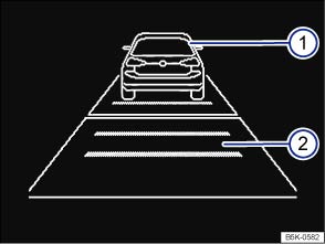 Fig. 156 In the instrument cluster display: ACC deactivated temporarily; vehicle detected ahead, time interval set (displayed in color on an instrument cluster with color display).
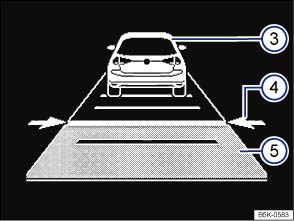 Fig. 157 In the instrument cluster display: ACC active, vehicle detected ahead, time interval is being set (displayed in color on an instrument cluster with color display).Read and follow the introductory information and safety information first⇒Introduction to the subject
Key to ⇒ Fig. 156 or ⇒ Fig. 157 :
Vehicle detected ahead (ACC inactive)Selected distance range (ACC inactive)Vehicle detected ahead when ACC is activeSetting the time interval to the vehicle ahead while traveling at the stored speedTime interval to the vehicle ahead while traveling at the stored speed has been set| Lights up |
Possible cause ⇒
|
Action |
|---|---|---|
|
|
The deceleration of the ACC automatic braking system is not sufficient to bring the vehicle to a full stop in time. | Depress the brake pedal! Driver intervention warning! |
|
|
ACC currently not available. | Park your vehicle and turn the engine off and on again. Check the sensor for damages or soiling. If the system is still not available, have it checked by an authorized Volkswagen dealer or authorized Volkswagen Service Facility. |
|
|
ACC is active. No vehicle has been detected ahead. The system is regulating vehicle speed. | – |
|
|
When displayed in white: ACC active. Vehicle detected ahead. ACC regulates the speed and the distance from the vehicle ahead. | – |
| When displayed in grey: ACC not active. System switched on, does not regulate. | ||
|
|
ACC is switched on and active. | – |
When the ignition is switched on, several warning and indicator lights come on briefly for a function check. They go out after a few seconds.
WarningFailure to heed warning lights and instrument cluster text messages can cause the vehicle to break down in traffic and result in a collision and serious personal injury.
NoteFailure to heed warning lights or text WARNINGS can result in vehicle damage.When the ACC is switched on, the display in the instrument cluster can be overwritten by other functions, for example, incoming telephone calls.
Displayed in color on an instrument cluster with color display.
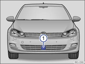 Fig. 158 In the front bumper: Radar sensor.
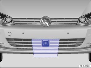 Fig. 159 Area around the radar sensor to be kept clean and free of obstructions.Read and follow the introductory information and safety information first⇒Introduction to the subject
Vehicles equipped with ACC have a radar sensor below the front bumper to monitor the traffic situation ⇒ Fig. 158① . The sensor can detect moving vehicles up to about 130 yards (120 m) in front of your vehicle.
The radar sensor function can be impaired by things such as mud, slush, or snow, or by conditions such as heavy rain or spray. In cases like these, the ACC may not work. The driver message ACC not available appears in the instrument cluster display. Clean the radar sensor as required ⇒ .
The ACC will automatically be available again as soon as the radar sensor is no longer impaired. The message in the instrument cluster display turns off.
The area in front of and around the radar sensor ⇒ Fig. 158① must not be covered by objects such as stickers, additional headlights, a license plate bracket, or other things, as these items can impair the function of the ACC system.
Any structural modifications to the vehicle, for example, lowering the vehicle or alterations to the front end trim, can impair the function of the ACC system. Structural modifications should only be carried out by a qualified workshop ⇒ Parts, accessories, repairs, and modifications . Contact an authorized Volkswagen dealer or an authorized Volkswagen Service Facility for assistance.
Incorrectly performed repairs to the front end of the vehicle can change the position of the radar sensor and therefore impair the function of the ACC system. Repair work should only be carried out by a qualified workshop. Contact an authorized Volkswagen dealer or an authorized Volkswagen Service Facility for assistance.
NoteIf you notice that the Adaptive Cruise Control (ACC) or Front Assist doesn't work properly, or if you suspect that the radar sensor has been damaged or if its position has been changed, switch off ACC immediately. This can help prevent further damage. Contact an authorized Volkswagen dealer or an authorized Volkswagen Service Facility to have the radar sensor realigned.
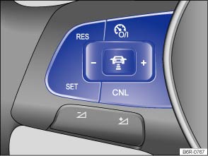 Fig. 160 Left-hand side of the multifunction steering wheel: Buttons for operating the Adaptive Cruise Control (ACC).Read and follow the introductory information and safety information first⇒Introduction to the subject
When the Adaptive Cruise Control (ACC) is switched on, the green indicator light comes on in the instrument cluster, and the ACC speed memory and status are shown in the display ⇒ Fig. 156 .
When switched on, the speed can be stored and set. The stored speed can vary from the speed actually being driven if the distance is being actively controlled.
| In order to: | You must: ⇒ Fig. 160 | Result: |
|---|---|---|
| Switch on ACC |
Press the |
The ACC is switched on, but not activated. |
| Activate ACC |
Press the |
The current speed is stored and controlled. |
| Temporarily deactivate ACC |
Briefly press the OR: Depress the brake pedal. OR: Press the |
Speed regulation is temporarily deactivated. The set speed is still stored. |
| Resume speed regulation (reactivate ACC) |
Press the |
The speed regulation resumes at the stored speed value. If no speed has yet been stored, the current speed is stored and controlled. |
| Increase set speed (while ACC is actively regulating vehicle speed) |
Press the Press briefly to increase the speed by 1 mph (1 km/h) and store it. Press and hold to increase the stored speed in increments of 5 mph (10 km/h) until you release the button. |
The vehicle accelerates until the new higher speed is reached and saves the new higher speed in the memory. |
| Reduce set speed (while ACC is actively regulating vehicle speed) |
Press the Press briefly to reduce the speed by 1 mph (1 km/h) and store it. Press and hold to reduce the stored speed in increments of 5 mph (10 km/h) until you release the button. |
Speed is reduced by accelerator release or automatic braking until the new lower speed is reached. |
| Switch off ACC |
Press and hold the |
The system is switched off and the stored speed is canceled. |
You can set the speed-dependent distance from the vehicle ahead to one of 5 levels.
In wet road conditions, you should always set a larger distance than when driving in dry road conditions.
The following distances can be selected:
The distance level to the vehicle ahead is set using the button on the multi-function steering wheel ⇒ Fig. 160 . The ACC display appears when the button is pressed ⇒ Display, warning and indicator lights . To set the distance level, press the
button.
When the highest level is reached, the distance returns to the lowest level when the button is pressed again.
The distance level can also be set using the or
buttons on the multi-function steering wheel immediately after the
button on the multi-function steering wheel ⇒ Fig. 160 has been pressed.
In the Infotainment system, you can set the distance level that should be selected when ACC is switched on by pressing the button followed by the
and Assistance systems function keys ⇒ Menu and system settings .
When ACC is active, the driving mode can influence the way the vehicle accelerates ⇒ Driving Mode Selection . On appropriately equipped vehicles, the following driving modes can be selected:
Danger!Following other vehicles too closely increases the risk of collisions and serious personal injury or even death.
WarningImproper use of the Adaptive Cruise Control can cause collisions, other accidents and serious personal injury.
The stored speed is canceled when the ignition or the ACC is switched off.ACC is automatically deactivated when ASR is switched off.
Read and follow the introductory information and safety information first⇒Introduction to the subject
Please deactivate ACC under following conditions due to system limitations ⇒ :
WarningNot deactivating Adaptive Cruise Control (ACC) in the situations mentioned above can cause collisions, other accidents, and serious personal injury.
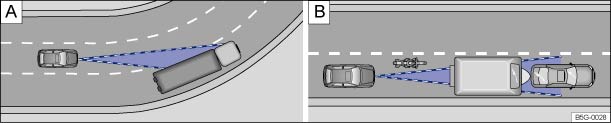 Fig. 161 Driving in a curve. Motorcycle traveling ahead outside of the sensor range.
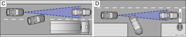 Fig. 162 Vehicle changing lanes. A turning and a stationary vehicle ahead.Read and follow the introductory information and safety information first⇒Introduction to the subject
Adaptive Cruise Control has physical and system-related limits. The driver may therefore feel that, in certain circumstances, some Adaptive Cruise Control reactions are unwanted or occur with a delay. You should therefore always be prepared to take full control of the vehicle whenever necessary.
If a vehicle traveling ahead brakes to a standstill, the ACC will also brake your vehicle to a standstill. The vehicle is then held stationary by the brakes for no more than a few seconds. You must press the brake pedal or the vehicle will start moving forward again!
After a stationary phase, press the button on the multi-function steering wheel and the Adaptive Cruise Control (ACC) will resume speed regulation as long as the vehicle in front is moving again.
If you switch on the turn signal when starting to pass another vehicle, Adaptive Cruise Control accelerates the vehicle automatically and reduces the distance to the vehicle in front.
If you move your vehicle into the passing lane and there is no vehicle ahead of you, the ACC will automatically increase the speed to your set level and maintain it.
Acceleration can be stopped at any time by depressing the brake pedal or pressing the button on the multi-function steering wheel ⇒ Operating Adaptive Cruise Control (ACC) .
When driving into a curve and driving out of a long curve, the radar sensor may react to a vehicle in the next lane ⇒ Fig. 161 . In such situations, the vehicle might decelerate unnecessarily or not react to the vehicle in front. In this case, you must either override the ACC by depressing the accelerator, interrupt the braking procedure by depressing the brake pedal, or press the
button on the multi-function steering wheel ⇒ Operating Adaptive Cruise Control (ACC) .
The function of the distance radar may be limited when driving in tunnels. Switch off ACC when driving through tunnels.
Narrow vehicles and vehicles traveling slightly to the left or right of your vehicle can only be detected by the radar sensor when they are within sensor range ⇒ Fig. 161 . This applies especially to narrow vehicles such as motorcycles. If required, brake the vehicle yourself.
Under certain circumstances, ACC will not correctly recognize vehicles carrying oversize loads or loads that exceed the vehicle dimensions, like flatbed trailer trucks.
Switch off ACC when driving behind or while passing such vehicles. If required, brake the vehicle yourself.
Vehicles that change into your lane within a short distance can only be detected by the radar sensor once they are within sensor range ⇒ Fig. 162 . The result is a delayed reaction by the Adaptive Cruise Control. If required, brake the vehicle yourself.
The ACC will not detect stationary obstacles, such as the end of a traffic jam or a broken down vehicle, or a vehicle approaching you in the same lane.
If a vehicle detected by Adaptive Cruise Control turns or changes lanes and there is a stationary vehicle in front of that vehicle, the system will not react to the stationary vehicle ⇒ Fig. 162 . If required, brake the vehicle yourself.
Narrow vehicles, such as motorcycles traveling ahead, are often detected late or not at all under some circumstances.
ACC does not detect oncoming vehicles in your lane.
Metal objects on the road, such as tracks or metal plates, can lead to unwanted reactions of the system, such as abrupt braking maneuvers.
If the radar sensor function is impaired by heavy rain, spray, snow or mud, Adaptive Cruise Control switches off temporarily. A driver information message appears in the instrument cluster display. Clean the radar sensors as required.
The Adaptive Cruise Control will automatically be available again as soon as the radar sensor is working properly. The message in the instrument cluster display switches off, and the Adaptive Cruise Control can be reactivated.
Strong reflected radiation of the radar signal, for example, in multilevel parking structures, can impair the function of the radar sensor.
Adaptive Cruise Control may switch off temporarily if the brakes overheat significantly, for example from braking maneuvers or driving down steep slopes. A driver information message appears in the instrument cluster display. Adaptive Cruise Control cannot be activated.
Adaptive Cruise Control can be activated again once the temperature of the brakes decreases sufficiently. The message in the instrument cluster display switches off. If the message does not go out for a long time, there is a fault.
If the message ACC not available does not switch off, there is a malfunction. Contact your authorized Volkswagen dealer or authorized Volkswagen Service Facility.
When towing a trailer, ACC and Front Assist may work only with limited functionality.
WarningIf ACC brings your vehicle to a complete stop before the system prompts you to brake and the stationary vehicle ahead starts moving, your vehicle will also start moving automatically. In some cases the radar sensor may be unable to detect obstacles in the vehicle's path. This can result in serious injury and accidents.
WarningThe view of the radar sensor can be impaired by rain, snow or heavy spray. Under certain circumstances, this could result in the vehicle ahead being detected inadequately or not at all. Take over yourself if necessary!
Introduction to the subjectIn this chapter you will find information on the following subjects:⇒ Driver warnings and Autonomous Emergency Braking ⇒ Radar sensor ⇒ Operating Front Assist ⇒ Temporarily switch off Front Assist in the following situations ⇒ System limits
Depending on vehicle equipment, the vehicle may be equipped with Forward Collision Warning (Front Assist), which includes Forward Collision Warning and Autonomous Emergency Braking systems.
The Forward Collision Warning system, when switched on, uses a radar sensor to help prevent rear-end collisions by providing a warning of a possible collision with a vehicle on the road ahead within physical and technical limits of the system.
When Front Assist is switched on, the Autonomous Emergency Braking system can automatically apply the brakes within the Front Assist speed range to help minimize the effects of a collision.
The Front Assist system is not a substitute for the driver's full concentration.
WarningThe Front Assist system technology cannot overcome the laws of physics and system-related limits. The driver is always responsible for braking in time. If the Front Assist system issues a warning, immediately apply the brake to slow the vehicle down or avoid the obstacle, depending on the traffic situation.
Deactivate Front Assist if it does not work as described in this chapter, for example, if multiple unwanted warnings occur. Have the system checked by an authorized Volkswagen dealer or authorized Volkswagen Service Facility.
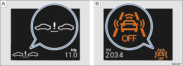 Fig. 163 Symbols in the instrument cluster display. : Distance warning. : System switched off (symbol displayed in color on an instrument cluster with color display).
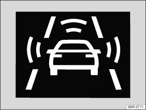 Fig. 164 In the instrument cluster display: Advance warning (symbol displayed in color on an instrument cluster with color display).Read and follow the introductory information and safety information first⇒Introduction to the subject
If the vehicle is traveling within a speed range of about 45–155 mph (70–250 km/h), the system warns the driver with a message in the instrument cluster display (⇒ Fig. 163 ) if it detects that the vehicle is driving too close to the vehicle ahead ⇒
. No acoustic warning will sound.
The warning period varies according to the traffic situation and your driving style.
Increase the distance between your vehicle and the vehicle ahead.
If the vehicle is traveling within a speed range of about 18–155 mph (30–250 km/h), the system warns the driver with a warning chime and a message in the instrument cluster display (⇒ Fig. 164 ) if it detects a possible collision with a vehicle ahead ⇒ .
The warning period varies according to the traffic situation and your driving style.
Brake or take action to avoid the vehicle ahead!
However, do not rely solely on Front Assist. Under certain conditions, the reactions of Front Assist may be unexpected or delayed from the driver's viewpoint. Always pay attention and take over if necessary ⇒ .
If you fail to respond to the advance warning, within a speed range of about 18–155 mph (30–250 km/h), Front Assist can initiate a short active braking maneuver, should you not react accordingly to an advance alert. In this case you will notice brief, jerky braking of the vehicle to warn you of an impending collision.
The moment of this alert can vary, depending on the traffic situation and the driving behavior.
If you should also fail to react to the immediate warning, within a speed range of about 3–155 mph (5–250 km/h), Front Assist can initiate an automatic braking maneuver that will abruptly decelerate the vehicle with elevated braking force. The emergency braking maneuver occurs shortly before a potential collision to reduce vehicle speed and help to minimize the effects of a collision.
In case of an impending collision, within a speed range of about 3–18 mph (5–30 km/h), Front Assist can initiate an automatic braking maneuver without the distance, advance, or immediate warnings to reduce vehicle speed and help to minimize the effects of a collision ⇒ .
The automatic braking maneuver occurs simultaneously with a warning in the instrument cluster display ⇒ Fig. 164 .
Front Assist can help to minimize the effects of a collision by supporting with additional braking force in case of an emergency braking situation within a speed range of about 3–155 mph (5–250 km/h), should the system detect that the force applied to the brake pedal by the driver is not sufficient to avoid a collision. In order for Front Assist to apply this support, it must have detected an impending collision with another vehicle ahead of yours and the brake pedal has to be hit hard and suddenly. However, this support only works as long as the brake pedal is depressed.
Front Assist considers the driver's response time to give warnings in time. This response time reduces automatically when the system, for example, detects movement of the accelerator or steering wheel. The system thus prevents unnecessary brake interventions, for example, when the driver passes another vehicle.
Front Assist cannot react when approaching standing objects ahead of you, for example, when driving up to a line of stopped vehicles in heavy traffic.
If the system is switched off, a text message and symbol appear in the instrument cluster display ⇒ Fig. 163 (magnified view).
WarningThe Front Assist technology cannot overcome the laws of physics and system-related limits. The driver is always responsible for braking in time. If the Front Assist system issues a warning, immediately apply the brake to slow the vehicle down or avoid the obstacle, depending on the traffic situation.
WarningFailure to heed warning lights and instrument cluster text messages can result in a collision and serious personal injury.
NoteIf you notice that Front Assist doesn't work properly or the sensor is damaged, switch off Front Assist immediately.
If Front Assist initiates a braking maneuver, the braking system is under pressure. In this case the braking pedal will feel harder and the brake pedal travel will be shorter.Automatic braking maneuvers can be interrupted by depressing the clutch or gas pedal, or by moving the steering wheel.Deactivate the Front Assist system if it does not work as described in this chapter, for example, if multiple unwanted warnings or braking maneuvers occur. Have the system checked by an authorized Volkswagen dealer or authorized Volkswagen Service Facility.When the Front Assist system is switched on, the display in the instrument cluster can be overwritten by displays related to other functions, for example, an incoming telephone call.The Autonomous Emergency Braking system can slow your vehicle down to a standstill, but not hold your vehicle permanently. When necessary, apply the vehicle brakes!Front Assist is automatically deactivated when ASR is switched off.
Displayed in color on an instrument cluster with color display.
Fig. 165 In the front bumper: Radar sensor.Fig. 166 Area around the radar sensor to be kept clean and free of obstructions.Read and follow the introductory information and safety information first⇒Introduction to the subject
A radar sensor mounted in the front bumper monitors traffic ⇒ Fig. 165① and can detect vehicles traveling ahead up to a distance of about 130 yards (120 m).
The radar sensor function can be impaired by things such as mud, slush, or snow, or by conditions such as heavy rain or spray. In cases like these, Front Assist will not work. The driver message Front Assist: no sensor view! appears in the instrument cluster display. Clean the radar sensor as required ⇒ .
The Front Assist system will automatically be available again as soon as the radar sensor is no longer impaired. The message in the instrument cluster display turns off.
The function of the Front Assist system can also be impaired when the radar signal radiation is reflected, for example, in multilevel parking structures, or by nearby metallic objects such as rails or metal plates in the road.
The area in front of and around the radar sensor ⇒ Fig. 166 must not be covered by objects such as stickers, additional headlights, a license plate bracket, or other things, as these items can impair the function of the Front Assist system.
Any structural modifications to the vehicle, for example, lowering the vehicle or alterations to the front end trim, can impair the function of the Front Assist system. Structural modifications should only be carried out by a qualified workshop ⇒ Parts, accessories, repairs, and modifications . Contact an authorized Volkswagen dealer or an authorized Volkswagen Service Facility for assistance.
Incorrectly performed repairs to the front end of the vehicle can change the position of the radar sensor and therefore impair the function of the Front Assist system. Repair work should only be carried out by a qualified workshop. Contact an authorized Volkswagen dealer or an authorized Volkswagen Service Facility for assistance.
NoteSwitch off the Front Assist system if you suspect that the radar sensor has been damaged or if its position has been changed. This can help prevent further damage. Contact an authorized Volkswagen dealer or an authorized Volkswagen Service Facility to have the radar sensor realigned.
Read and follow the introductory information and safety information first⇒Introduction to the subject
The Front Assist system is automatically active once the ignition is switched on ⇒ Starting and stopping the engine .
The advance warning and distance warning are automatically switched off when the Front Assist system is switched off.
Volkswagen recommends that the Front Assist system is switched on at all times, except in the specific situations described in this Manual ⇒ Temporarily switch off Front Assist in the following situations .
On appropriately equipped vehicles, you can turn the distance warning and the advance warning on or off in the Infotainment system by pressing the button followed by the
and Assistance systems function keys ⇒ Menu and system settings .
Via this menu, you can also adjust the warning period for the advance warning to one of three settings:
Volkswagen recommends that the distance and advance warnings are switched on at all times.
Read and follow the introductory information and safety information first⇒Introduction to the subject
Front Assist should be switched off in the following situations due to system limitations ⇒ :
WarningFailure to switch off Front Assist in the situations mentioned can cause accidents and serious personal injury.
Read and follow the introductory information and safety information first⇒Introduction to the subject
Front Assist has physical and system-related limits. The driver may therefore feel that, in certain circumstances, some Front Assist reactions are unwanted or occur with a delay. You should therefore always be prepared to take full control of the vehicle whenever necessary.
Introduction to the subjectIn this chapter you will find information on the following subjects:⇒ Display and indicator lights ⇒ How Lane Assist works ⇒ When to switch off Lane Assist ⇒ Driver information
Your vehicle may be equipped with a Lane Assist system, which can warn you if your vehicle unintentionally leaves the current drive lane.
WarningAlways remember that Lane Assist has limits – using Lane Assist when it is not possible to drive safely can be dangerous and can lead to an accident and serious personal injury.
WarningUnder certain circumstances, the Lane Assist may not be able to recognize all lane markings. Bad or wet roads, worn out markings, or objects on the road can lead to the Lane Assist not or mistakenly recognizing lane markings.
WarningIf the view area of the camera is covered or dirty, Lane Assist may not work properly.
NoteIn order to help maintain the proper function of Lane Assist:
Lane Assist has been developed only for on-road driving.If Lane Assist does not work properly and as described here or if there is a system fault, have the system checked by an authorized Volkswagen dealer or authorized Volkswagen Service Facility.
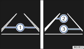 Fig. 167 In the instrument cluster display: Lane Assist display (displayed in color on an instrument cluster with color display).Read and follow the introductory information and safety information first⇒Introduction to the subject
Display fields ⇒ Fig. 167 :
Lane marking detected (shown in grey). No regulation is necessary.Lane marking detected (shown in white). System is actively regulating.No lane marking detected. System is not regulating.| Lights up | Possible cause |
|---|---|
|
|
Lane Assist is switched on but not active. The system cannot clearly detect the lane. Refer to ⇒ Driver information . |
|
|
Lane Assist is switched on and active. |
When the ignition is switched on, several warning and indicator lights come on briefly for a function check. They go out after a few seconds.
WarningFailure to heed warning lights and instrument cluster text messages can cause the vehicle to break down in traffic and result in a collision and serious personal injury.
NoteFailure to heed warning lights or text WARNINGS can result in vehicle damage.
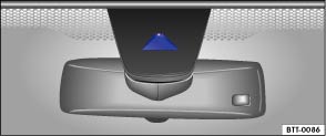 Fig. 168 In the front windshield: Area of the Lane Assist camera.Read and follow the introductory information and safety information first⇒Introduction to the subject
With the help of a camera ⇒ Fig. 168 , Lane Assist can recognize possible side markings of the current drive lane. Should the vehicle leave this area unintentionally, for example, when leaving the current drive lane without activating a turn signal, the system will warn you with a corrective steering intervention. The driver can override the corrective steering intervention at any time.
Lane Assist will not warn you of a lane change if you activate the turn signal, because the system will assume that the lane change is happening intentionally.
The following (very rare) situations will cause the steering wheel to vibrate and demand active steering intervention by the driver:
The indicator light in the instrument cluster shows the status of the system.
Automatic deactivation: The Lane Assist system can switch off automatically if there is a system fault. The indicator light goes out.
Before starting to drive, always make sure that the area of the camera ⇒ Fig. 168 is not covered. Keep this area clean at all times.
Read and follow the introductory information and safety information first⇒Introduction to the subject
Please deactivate Lane Assist under following conditions ⇒ :
WarningNot deactivating Lane Assist in the situations mentioned above can cause collisions, other accidents and serious personal injury.
Read and follow the introductory information and safety information first⇒Introduction to the subject
Under certain circumstances Lane Assist can be deactivated automatically:
Introduction to the subjectIn this chapter you will find information on the following subjects:⇒ Special considerations ⇒ Camera ⇒ Operation ⇒ Parking
Depending on equipment, your vehicle may be equipped with a Rear View Camera system.
A camera in the trunk lid assists the driver while backing up or maneuvering. The camera image is shown together with the orientation lines projected by the system on the screen of the factory-installed Infotainment system.
The Rear View Camera system may take a few seconds to bring up the camera image.
The functions and displays of the Rear View Camera system may vary on vehicles with or without Park Distance Control (PDC) ⇒ Park Distance Control (PDC) .
WarningThe Rear View Camera system is not able to give you a clear and undistorted view of all areas behind the vehicle.
WarningThe Rear View Camera system technology cannot overcome the laws of physics and the limits of the system. Careless or unintentional use of the Rear View Camera system may result in accidents and severe injuries.
Note
Read and follow the introductory information and safety information first⇒Introduction to the subject
The trunk lid must be closed.
A reliable and clear image must be displayed and the camera lens must be clean .
There must be a clear and complete view of the area behind the vehicle.
The rear of the vehicle must not be heavily loaded.
The driver must be familiar with the system.
The position of the camera has not changed, such as after a rear-end collision. If the position of the camera has changed, have the system checked by an authorized Volkswagen dealer or an authorized Volkswagen Service Facility.
Volkswagen recommends practicing parking and maneuvering with the Rear View Camera system in a safe place with little or no traffic or in a parking lot under good visibility and weather conditions to familiarize yourself with the system, the orientation lines, and the way they work.
Depending on equipment, various settings, including brightness, contrast, and color, can be adjusted by moving your hand toward the Infotainment system screen and tapping the function keys - or +, or by moving the corresponding slider.
To change the settings follow these instructions:
It is not possible to open the trunk lid if the Volkswagen emblem is folded out.
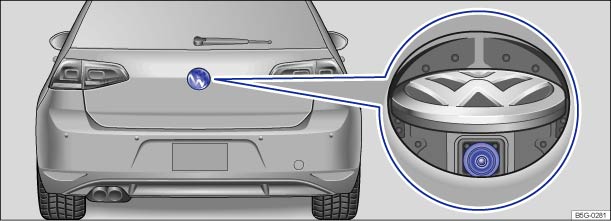 Fig. 169 In the trunk lid: Location of the camera.Read and follow the introductory information and safety information first⇒Introduction to the subject
The camera ⇒ Fig. 169 (magnified view) displays only two-dimensional images. Recesses and protruding objects on the ground or protruding parts on other vehicles may be difficult or impossible to identify due to the lack of depth of field.
Objects or another vehicle may seem closer or farther away on the screen than they really are.
| Examples of optical distortion by the camera: |
|---|
| – When driving from a level surface onto an upward or downward slope. |
| – When driving up or down a slope onto a level surface. |
| – If the rear of the vehicle is heavily loaded. |
| – When approaching protruding objects. These objects can disappear from the field of view when backing up. |
Keep the camera lens clean and free of snow and ice:
. .Note
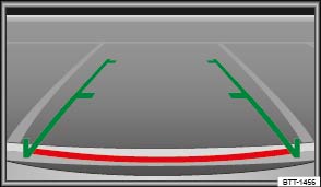 Fig. 170 In the Infotainment system: Rear View Camera system display (may vary depending on vehicle equipment).Read and follow the introductory information and safety information first⇒Introduction to the subject
The following function buttons appear when you move your hand toward the screen. Buttons may vary, depending on vehicle equipment.
| Key for displays ⇒ Fig. 170 | |
|---|---|
| Symbol | Meaning |
|
|
Depending on vehicle equipment: Switch the PDC display on. |
|
|
Depending on vehicle equipment: Switch the PDC display off. |
|
|
Close the current display. |
|
|
Depending on vehicle equipment: Switch the PDC sound on or off. |
|
|
Setting display: brightness, contrast, color. |
|
|
Depending on vehicle equipment: Display PDC. |
The Rear View Camera system switches on and off automatically.
| Function | Action with the ignition on | |
|---|---|---|
| Vehicles without Park Distance Control | Vehicles with Park Distance Control | |
| Switch on the display automatically: | Shift into Reverse (R). | Shift into Reverse (R). |
| Switch off the display automatically: | Switch off the ignition. | Switch off the ignition. |
| OR: Drive forward faster than 6 mph (10 km/h) or for longer than 10 seconds. | OR: Drive forward faster than 6 mph (10 km/h) or for longer than 10 seconds. | |
| OR: Shift out of Reverse (R) and wait about 10 seconds. | OR: Shift out of Reverse (R) (display switches off immediately). | |
| Switch off the display manually: |
Press one of the Infotainment system buttons or move your hand toward the screen and tap the |
Press one of the Infotainment system buttons or move your hand toward the screen and tap the |
|
OR: Move your hand toward the screen and tap the |
||
| Show the display again: | Shift out of Reverse (R), then shift back into Reverse (R). | Shift out of Reverse (R), then shift back into Reverse (R). |
|
OR: Move your hand toward the screen and tap the |
||
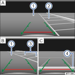 Fig. 171 On the screen: Orientation lines for the parking space behind the vehicle. : Searching for a parking space, : Backing into the parking space, : Maneuvering.Read and follow the introductory information and safety information first⇒Introduction to the subject
| Key to ⇒ Fig. 171 : | |
|---|---|
| Meaning | |
| — | Lateral green lines: Projection of the vehicle (widened somewhat) toward the rear. The green lines stop about 6 feet (2 meters) behind the vehicle on the road. |
| — | Horizontal red line: Safety distance (area up to about 16 inches (40 cm) behind the vehicle on the road). |
| ① | Road. |
| ② | Selected parking space. |
| ③ | Side lines of the selected parking space. |
| ④ | Rear boundary of the parking space, such as a curb. |
All references to orientation line length apply to vehicles on a horizontal surface.
| Step | Action |
|---|---|
| 1. | The requirements for parking and maneuvering with the Rear View Camera system must be fulfilled ⇒ Special considerations . |
| 2. |
Position the vehicle in front of the parking space ② ⇒ Fig. 171 |
| 3. | Shift into Reverse (R). |
| 4. |
Reverse slowly and steer the vehicle |
|
Pay attention to the message in the display: Look! Safe to move? ⇒
|
|
| 5. |
Align the vehicle in the parking space |
| 6. |
Stop the vehicle |
NoteSmaller objects up to about 20 inches (50 cm) from the rear of the vehicle will not be detected by the camera and could result in vehicle damage.
Introduction to the subjectIn this chapter you will find information on the following subjects:⇒ Operation ⇒ PDC signal chimes and displays ⇒ Vehicle path display ⇒ PDC menu
Depending on equipment, the vehicle may be equipped with the Park Distance Control system (PDC).
The Park Distance Control (PDC) system can help the driver when backing up and parking. PDC uses ultrasonic sensors in the bumpers to measure the distance between the vehicle and objects. The system uses the time it takes for the ultrasonic waves to bounce back from the object to calculate the distance between the vehicle and an object. PDC works only at speeds up to about 5–10 mph (10–15 km/h).
If the vehicle gets too close to an obstacle behind it, a beeping signal sounds. The closer the vehicle gets to the obstacle, the faster the beep. When the obstacle is very close, the sound is continuous.
If you move even closer to the obstacle despite the continuous warning sound, the system cannot measure the distance remaining until collision.
A Declaration of Compliance with United States FCC and Industry Canada regulations is found in the Consumer information section of this Manual ⇒ Consumer information .
WarningPark Distance Control is no substitute for careful and attentive driving. Never rely completely on these systems for information about people and objects that might be in the way of the vehicle and could be struck resulting in serious personal injuries.
Note
Volkswagen recommends practicing with the Park Distance Control system in a location or parking space with no traffic in order to become familiar with the system and how it works.If an ultrasonic sensor malfunctions, the corresponding sensor area is switched off and cannot be reactivated until the malfunction is corrected (depending on vehicle equipment). Have the system checked by an authorized Volkswagen dealer or an authorized Volkswagen Service Facility.If you hear a long beep of about 3 seconds when you first turn PDC on or the indicator light in the button starts blinking, there is a malfunction in the Park Distance Control system. Switch off the Park Distance Control system with the button and have it checked by an authorized Volkswagen dealer or an authorized Volkswagen Service Facility.
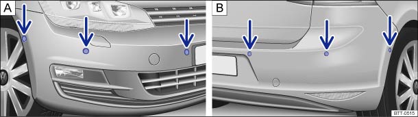 Fig. 172 In the front and rear bumpers: Park Distance Control system sensors.
 Fig. 173 In the lower center console: Button to switch the Park Distance Control system on or off.Read and follow the introductory information and safety information first⇒Introduction to the subject
The Park Distance Control (PDC) uses ultrasonic sensors to determine the distance from the front or rear bumpers to an obstacle. Depending on vehicle equipment, there are either 4 or 6 sensors for the PDC located in the rear bumper () and additional sensors in the front bumper (
) ⇒ Fig. 172 (arrows).
The intermittent and permanent signal chimes given by the front PDC sensors are of a higher pitch than those given by the rear PDC sensors. This is a standard feature.
The warning signals can be adjusted in the Infotainment system menu ⇒ Infotainment system .
| In order to | Operation (when the ignition is switched on) |
|---|---|
| Manually activate PDC: |
Press the |
| Manually deactivate PDC: |
Press the |
| Manually deactivate the display (sound stays active): | Press a function selection button on the factory-installed Infotainment system ⇒BookletInfotainment System,. |
|
OR: Move your hand toward the screen and tap the |
|
| Automatically activate PDC: | Shift into Reverse (R). |
| OR: Depending on vehicle equipment, when the vehicle rolls backwards. | |
| OR: Depending on vehicle equipment, when slowly driving toward an obstacle located in the scanned area in front of the vehicle at a speed below 6–9 mph (10–15 km/h) ⇒ PDC signal chimes and displays when automatic activation is switched on in the Infotainment system. A miniature PDC view may be displayed. | |
| Automatically deactivate PDC: | Shift into Park (P). |
| OR: Drive forward faster than about 5–10 mph (10–15 km/h). | |
| Mute the PDC volume: |
Move your hand toward the screen and tap the |
| OR: Switch on the electronic parking brake (if equipped). | |
| Switch from mini PDC display to full-screen mode. | Shift into Reverse (R). |
| OR: Depending on vehicle equipment, when the vehicle rolls backwards. | |
| OR: Move your hand toward the screen and tap the mini PDC function key. | |
| Switch to the Rear View Camera system display (if equipped): | Shift into Reverse (R). |
|
OR: Move your hand toward the screen and tap the |
The indicator light in the button ⇒ Fig. 173 lights up and stays on as long as the feature is active.
When the PDC is activated automatically, a mini PDC display appears on the left-hand side of the screen ⇒ Fig. 175 .
Automatic activation of the PDC when driving slowly towards an obstacle located in front of the vehicle only works when the speed falls below about 6–9 mph (10–15 km/h) for the first time. If the PDC was switched off using the button, performing one of the following actions with the ignition switched on can automatically reactivate the PDC:
Automatic activation of the mini PDC display can be turned on or off in the Infotainment system ⇒ Infotainment system .
When the box in the automatic activation function key is checked , signal chimes sound from a distance of about 20 inches (50 cm) from the obstacle.
WarningNever rely completely on the PDC for information about people and objects that might be in the way of the vehicle and could be struck by the vehicle causing serious personal injury.
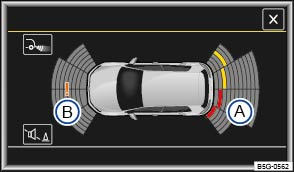 Fig. 174 PDC display of the area surrounding the vehicle.
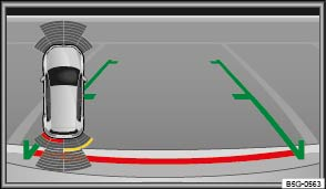 Fig. 175 Mini PDC display of the area surrounding the vehicle (display may vary depending on vehicle equipment).Read and follow the introductory information and safety information first⇒Introduction to the subject
| Key to elements in the color display | |
|---|---|
| ⇒ Fig. 174 and ⇒ Fig. 175 | Meaning |
| Ⓐ | Scanned area behind the vehicle. |
| Ⓑ | Scanned area in front of the vehicle. |
|
|
A yellow segment represents an obstacle in the vehicle’s path. |
|
|
A red segment depicts an obstacle located close to the vehicle. |
|
|
A grey segment represents an obstacle outside of the vehicle's path. |
|
|
System fault in the scanned area. |
|
|
Temporary malfunction in the scanned area, depending on vehicle equipment (not pictured). |
When the factory-installed Infotainment system is switched on, the areas to the front and rear of the vehicle that are scanned by ultrasonic sensors are shown on the screen ⇒ Fig. 174 . The positions of potential obstacles are displayed relative to the vehicle ⇒ .
When the vehicle approaches an obstacle located in the range of the ultrasonic sensors, there are audible signal chimes. An intermittent signal chime means that a sufficiently short distance between the vehicle and an obstacle is detected. The shorter the distance, the shorter the intervals between the chimes. The signal chime will sound continuously if the obstacle is very close.
When there is an imminent risk of collision at the front area of the vehicle, the signal chimes beep at the front of the vehicle. When there is a risk of imminent collision at the rear area of the vehicle, the signal chimes beep at the rear of the vehicle.
If you continue to drive the vehicle closer to the obstacle despite a continuous signal chime, the system will no longer be able to measure the distance.
The intermittent signal chime volume decreases after a few seconds if the distance remains the same. The volume remains constant if the signal chime is continuous. As soon as the vehicle moves away from an obstacle again, the intermittent signal chime switches off automatically. If the vehicle moves towards an obstruction again, the intermittent signal chimes beep automatically.
The graphic on the screen displays the scanned areas in several segments. The closer the vehicle drives towards an obstacle, the closer the segment will move to the vehicle in the display. The collision area has been reached at the latest when the second to last segment is displayed. Do not keep driving!
| Vehicles with PDC at the front and rear | |||||
|---|---|---|---|---|---|
| Area of the vehicle | Distance of vehicle from obstacle | Signal tone | Segment color if obstacle is detected (color display only) | ||
| Ⓐ | Rear center | Obstacle not in the vehicle’s path |
about 12 – 63 in. (31 – 160 cm) |
– | Grey |
| Rear side |
about 12 – 23 in. (31 – 60 cm) |
||||
| Ⓑ | Front center |
about 12 – 47 in. (31 – 120 cm) |
|||
| Front side |
about 12 – 23 in. (31 – 60 cm) |
||||
| Ⓐ | Rear center | Obstacle in the vehicle’s path |
about 12 – 63 in. (31 – 160 cm) |
Intermittent tone | Yellow |
| Rear side |
about 12 – 23 in. (31 – 60 cm) |
||||
| Ⓑ | Front center |
about 12 – 47 in. (31 – 120 cm) |
|||
| Front side |
about 12 – 23 in. (31 – 60 cm) |
||||
| Ⓐ, Ⓑ | Obstacle outside of the collision area |
about 0 – 12 in. (0 – 30 cm) |
Intermittent tone | Red | |
| Ⓐ, Ⓑ | Obstacle in the collision area |
about 0 – 12 in. (0 – 30 cm) |
Constant tone | Red | |
You can mute the PDC beeping signals by moving your hand toward the Infotainment system screen and tapping the function key (if applicable). Tap the function key again to turn the beeping signals back on.
Switching Park Distance Control back on after it was switched off reactivates the volume. System malfunction warning signals cannot be switched off.
If you manually deactivate the display, PDC remains on and the sound is reactivated.
Switching on the electronic parking brake also mutes the PDC volume.
The mute setting is active if the PDC was switched on using the button when the selector lever is in Park (P).
WarningNever pay so much attention to the graphics shown on the screen that you fail to notice what is going on around you.NoteFailure to observe the illuminated text messages can lead to the vehicle being damaged.It can take a few seconds before the area scanned by the sensors is displayed on the Infotainment system screen.
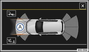 Fig. 176 PDC display (depending on vehicle equipment): Vehicle path display without steering input.
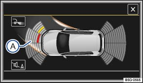 Fig. 177 PDC display (depending on vehicle equipment): Vehicle path display with steering input.Read and follow the introductory information and safety information first⇒Introduction to the subject
Depending on equipment, the vehicle path may not be displayed on the Infotainment system screen.
| Key to the main elements in the color display: | |
|---|---|
| ⇒ Fig. 176 and ⇒ Fig. 177 | Meaning |
| Ⓐ | Vehicle path display. |
|
|
A yellow segment represents an obstacle in the vehicle’s path. |
|
|
A red segment represents an obstacle close to the vehicle. |
|
|
A grey segment represents an obstacle outside of the vehicle's path. |
| Function | Operation (when the ignition is switched on) |
|---|---|
| Front vehicle path display | Forward gear engaged. |
| OR: Shift to Neutral (N). | |
| OR: Depending on vehicle equipment, roll forward. | |
| Rear vehicle path display | Select the Reverse (R) gear. |
| OR: Depending on vehicle equipment, roll backward. |
The vehicle path display changes in relation to the input from the steering system. Obstacles that are located in the vehicle's path, depending on the current steering angle, are displayed in yellow and red segments.
Obstacles that are no longer in the vehicle's path, depending on the current steering angle, are displayed as follows:
When the selector lever is in position P and the PDC is activated, all segments representing an obstacle are displayed in grey and the vehicle path display is hidden.
When the electronic parking brake is engaged, all segments symbolizing an obstruction are displayed in grey, and the vehicle path display is hidden.
NoteIf an ultrasonic sensor malfunctions, the vehicle path display is switched off and cannot be reactivated until the malfunction is corrected.
Read and follow the introductory information and safety information first⇒Introduction to the subject
Switch on the ignition.
If necessary, switch on the Infotainment system.
Press the button.
Tap the function key.
Tap the Parking and maneuvering function key.
Select the required settings in the ParkPilot menu.
| Function key | Action |
|---|---|
| Automatic activation |
If the box in the function key is checked |
| Front volume | Set different volumes for the front signal chimes by tapping the - or + function keys or by adjusting the control. |
| Front pitch | Set different pitches for the front signal chimes by tapping the - or + function keys or by adjusting the control. |
| Rear volume | Set different volumes for the rear signal chimes by tapping the - or + function keys or by adjusting the control. |
| Rear pitch | Set different pitches for the rear signal chimes by tapping the - or + function keys or by adjusting the control. |
| Audio lowering | Set the level to which the Infotainment system volume should be lowered when the PDC is active: |
| Off: The Infotainment system volume is not lowered. | |
| 1-5: The Infotainment system volume is lowered slightly to medium, depending on the number selected. | |
| Mute: The Infotainment system volume is muted. |
Introduction to the subjectIn this chapter you will find information on the following subjects:⇒ Description of the Park Assist system ⇒ Parking while using the Park Assist system ⇒ Driving out of a parallel parking space using Park Assist ⇒ Park Assist automatic braking
The Park Assist system is an extension of the Park Distance Control system ⇒ Park Distance Control (PDC) and can assist the driver when:
In vehicles with Park Distance Control (PDC), the display of the scanned area to the front, rear, and sides of the vehicle is shown on the screen of the factory-installed Infotainment system. Within the system limits, the position of obstacles can be shown in relation to the vehicle.
The Park Assist system has certain system-related limitations. The driver should exercise caution when using the Park Assist system ⇒ .
WarningPark Assist technology cannot overcome the laws of physics and the limits of the system. Do not let the extra convenience Park Assist can provide tempt you into taking extra risks. The system is not a substitute for the driver's full concentration.
WarningMaking quick turning movements of the steering wheel when parking or driving out of a parking space can cause serious injuries.
Note
NoteIf an ultrasonic sensor fails, the corresponding area of the ultrasonic sensor cluster is switched off and cannot be reactivated until the fault has been corrected. Have the system checked by an authorized Volkswagen dealer or an authorized Volkswagen Service Facility.Always keep the ultrasonic sensors in the bumpers clean and free of ice, dirt, and snow. Do not cover the sensors with stickers or other objects, as these may prevent the system from working properly.Volkswagen recommends practicing with the Park Assist system in a location or parking space with no traffic in order to become familiar with the system and how it works.When parking or driving out of a parking space, the system gives a signal tone to tell the driver to switch between driving forward and reversing. The driver should not wait until the Park Distance Control sounds continuously before changing direction.If the Park Assist system turns the steering wheel when the vehicle is stationary, the symbol appears in the instrument cluster display as well. Depress the brake pedal so that the steering movement takes place with the vehicle stationary, keeping the required number of parking maneuvers to a minimum.
 Fig. 178 In the lower center console: Button for switching on the Park Assist system.Read and follow the introductory information and safety information first⇒Introduction to the subject
Park Assist consists of ultrasonic sensors in the front and rear bumpers and the button ⇒ Fig. 178 , which turns the Park Assist system and the instrument cluster display on and off.
The Park Assist system cancels the procedure of parking or driving out of a parking space if one of the following occurs:
If none of the above situations apply, resume Park Assist by pressing the button once more.
The Park Assist system has system-related limitations. For example, if there is a tight curve in the road, the Park Assist system cannot help you park the vehicle or drive out of a parking space.
If after a wheel has been changed, you notice that the system does not park the vehicle or leave a parking space as well as it did before the wheel was changed, the new wheel dimensions may need to be synchronized with the system. The synchronization process happens automatically while the vehicle is in motion. To help the system synchronize the new wheel, drive around curves slowly at speeds of less than about 12 mph (20 km/h) ⇒ .
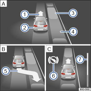 Fig. 179 In the instrument cluster display: Parallel parking. Searching for a parking space, positioning the vehicle for parking, maneuvering.
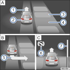 Fig. 180 In the instrument cluster display: Parking perpendicular to the road. Searching for a parking space, positioning the vehicle for parking, maneuvering.Read and follow the introductory information and safety information first⇒Introduction to the subject
Key to ⇒ Fig. 179 and ⇒ Fig. 180 :
Prompt to drive forwardYour vehicleParked vehiclesParking space detectedArrow indicating the parking suggestion (prompt to park)Prompt to press the brake pedalProgress barThe progress bar ⇒ Fig. 179⑦ or ⇒ Fig. 180⑦ in the instrument cluster display shows the relative remaining distance using symbols. The higher the progress bar, the longer the remaining distance. When driving forward, the progress level moves up; when driving in reverse, it moves down.
| For parking spaces parallel to the side of the road | For parking spaces perpendicular to the side of the road |
|---|---|
| The ASR must be switched on ⇒ Braking and parking . | The ASR must be switched on ⇒ Braking and parking . |
| Do not go faster than about 25 mph (40 km/h) when driving past the parking space. | Do not go faster than about 12 mph (20 km/h) when driving past the parking space. |
| Maintain a distance of 1.6–6.5 feet (0.5–2 meters) when driving past the parking space. | Maintain a distance of 1.6–6.5 feet (0.5–2 meters) when driving past the parking space. |
| Length of the parking space: vehicle length + 3.3 feet (1.0 meters). | Width of the parking space: vehicle width + 2.6 feet (0.8 meters). |
| Do not go faster than about 4 mph (7 km/h) when parking. | Do not go faster than about 4 mph (7 km/h) when parking. |
Complete the following steps:
| Step | For parking spaces parallel to the side of the road ⇒ Fig. 179 | For parking spaces perpendicular to the side of the road ⇒ Fig. 180 |
|---|---|---|
| 1. | Requirements for parking using Park Assist must be fulfilled⇒ Requirements for parking using Park Assist . | |
| 2. |
Press the |
Press the |
|
An indicator light comes on in the |
||
| 3. |
Press the |
|
| 4. | Activate the turn signal for the side of the street on which you want to park. The corresponding side of the street is shown in the instrument cluster display. | |
| 5. | Follow the messages in the instrument cluster display while observing traffic, and drive the vehicle past the parking space. | |
| 6. |
Watch the instrument cluster display to see if the parking space has been determined suitable and whether the vehicle has reached the correct position for parking |
|
| The parking space is only determined suitable when the instrument cluster displays the prompt to park ⑤. | ||
| 7. | Stop the vehicle and after a short stationary period, move the selector lever to Reverse (R). | |
| 8. |
Release the steering wheel when the following message is shown ⇒ Steer. interv. Check area around veh.!
|
|
| Check the area around the vehicle and carefully depress the accelerator pedal. Do not exceed 4 mph (7 km/h). | ||
| The Park Assist system will only operate the steering wheel during the parking procedure. The driver controls the accelerator, the brake, and the transmission selector lever. | ||
| 9. | Reverse the vehicle until there is a continuous tone from the Park Distance Control (PDC) system. | |
| OR: Until the prompt to drive forward appears in the instrument cluster display. | ||
| OR: Until the message Park Assist finished! appears in the instrument cluster display. | ||
|
The progress bar ⑦ |
||
| 10. | Press the brake pedal until Park Assist has finished steering. | |
|
OR: Until the |
||
| 11. | Drive the vehicle forward until there is a continuous tone from the Park Distance Control (PDC) system. | |
| OR: Until the prompt to drive in reverse appears in the instrument cluster display. | ||
|
The Park Assist system will guide the vehicle when driving forward and reversing |
||
| 12. | Wait until Park Assist has completed turning the steering wheel at the end of each parking maneuver to achieve an optimal parking result. | |
| A message is displayed in the instrument cluster once parking is completed. A signal tone may also sound. | ||
Stopping the maneuver too soon while parking could lead to less than optimal parking results.If there is not enough space to maneuver the vehicle, the suggested parking space may still be indicated in the instrument cluster display. However, you will not be prompted to park.The Park Assist system can also be activated after driving past a parallel parking space at less than about 25 mph (40 km/h) or a perpendicular parking space at less than about 12 mph (20 km/h) and then pressing the button.
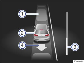 Fig. 181 In the instrument cluster display: Driving out of a parallel parking space.Read and follow the introductory information and safety information first⇒Introduction to the subject
Key to ⇒ Fig. 181 :
Parked vehiclesYour vehicle with reverse gear engagedProgress barArrow indicating the suggested procedure for driving out of a spaceComplete the following steps:
| Step | For parallel parking spaces only |
|---|---|
| 1. | The requirements for driving out of a parking space using Park Assist must be fulfilled ⇒ Requirements for driving out of a parallel parking space using Park Assist . |
| 2. | Start the engine ⇒ Starting and stopping the engine . |
| 3. |
Press the |
|
An indicator light comes on in the |
|
| 4. | Use the turn signal lever to select the direction (left or right) in which you would like to drive out of the parking space. |
| 5. | Move the selector lever to Reverse (R). |
|
Release the steering wheel when the following message is shown ⇒ Steer. interv. Check area around veh.!
|
|
| Check the area around the vehicle and carefully depress the accelerator pedal. Do not exceed 4 mph (7 km/h). | |
| The Park Assist system will only operate the steering wheel while driving out of the parking space. The driver controls the accelerator, the brake, and the transmission selector lever. | |
| 6. | Reverse the vehicle until there is a continuous tone from the Park Distance Control (PDC) system. |
| OR: Until the prompt to drive forward appears in the instrument cluster display. | |
| The progress bar ⇒ Fig. 181③ displays the distance left to be traveled ⇒ Progress bar . | |
| 7. | Press the brake pedal until the Park Assist system has finished steering. |
|
OR: Until the |
|
| 8. | Drive the vehicle forward until there is a continuous tone from the Park Distance Control (PDC) system. |
| OR: Until the prompt to drive in reverse appears in the instrument cluster display. | |
| The Park Assist system steers the vehicle when driving forward or reversing until the vehicle can be driven out of the parking space. | |
| 9. | A message is displayed in the instrument cluster when the vehicle can be driven out of the parking space. A signal tone may also sound. |
| Take over steering with the steering angle turned by the Park Assist system. | |
| 10. | When traffic permits, drive the vehicle out of the parking space. |
Read and follow the introductory information and safety information first⇒Introduction to the subject
Park Assist can help the driver by braking automatically in certain situations.
The driver is always responsible for braking in time ⇒ .
An automatic brake intervention may occur to prevent the vehicle from exceeding a speed of about 4 mph (7 km/h) when parking or driving out of a parking space. You can continue the maneuver to park or drive out of a parking space after the automatic brake intervention.
Automatic brake intervention occurs no more than one time per parking maneuver. The parking maneuver is interrupted if the vehicle speed exceeds 4 mph (7 km/h) again.
Depending on certain conditions such as weather, vehicle condition, vehicle load, or vehicle angle, the Park Assist system can bring the vehicle to a stop before it reaches an obstruction. Depress the brake pedal⇒ !
An automatic brake intervention to minimize damage ends the current parking maneuver.
WarningPark Assist technology cannot overcome the laws of physics and the limits of the system. Do not let the extra convenience Park Assist can provide tempt you into taking extra risks. The system is not a substitute for the driver's full concentration.
Introduction to the subjectIn this chapter you will find information on the following subjects:⇒ Indicator lights ⇒ Blind Spot Monitor ⇒ Driving situations ⇒ Rear Traffic Alert ⇒ Using the Blind Spot Monitor with Rear Traffic Alert
Depending on vehicle equipment, the vehicle may be equipped with the Blind Spot Monitor system.
The Blind Spot Monitor assists the driver by using radar sensors to monitor the traffic in the blind spot detection area as well as traffic behind the vehicle.
The integrated Rear Traffic Alert system can help the driver when backing out of parking spaces and when maneuvering.
The Blind Spot Monitor is only designed for use on paved roads.
WarningThe Blind Spot Monitor with Rear Traffic Alert technology cannot overcome the laws of physics and limits of the system. Careless or unintentional use of the Blind Spot Monitor and Rear Traffic Alert may result in accidents and serious injuries.
Note
If the system does not function as described in this chapter or if your vehicle was involved in a collision, do not use the Blind Spot Monitor with Rear Traffic Alert. See an authorized Volkswagen dealer or an authorized Volkswagen Service Facility to have the system checked.
Read and follow the introductory information and safety information first⇒Introduction to the subject
| Lights up | Possible cause | Action |
|---|---|---|
|
|
Blind Spot Monitor malfunction. | Contact an authorized Volkswagen dealer or authorized Volkswagen Service Facility for assistance. |
| Lights up | Possible cause |
|---|---|
|
|
Lights up briefly: The Blind Spot Monitor is active and ready. |
| Lights up and stays on: The Blind Spot Monitor detects a vehicle in the blind spot. |
| Flashes | Possible cause |
|---|---|
|
|
A vehicle is detected in the blind spot, and the turn signal on that side of the vehicle is switched on ⇒ .
|
When the ignition is switched on, several warning and indicator lights come on briefly for a function check. They go out after a few seconds.
If the indicator light in the outside mirror does not light up, the Blind Spot Monitor does not currently detect a vehicle in the monitored area around your vehicle ⇒ .
The brightness of the indicator lights in the outside mirrors are dimmed when the headlights are switched on (night mode).
WarningFailure to heed warning and indicator lights and instrument cluster text messages can result in a collision and serious personal injury.
NoteFailure to heed warning and indicator lights or text WARNINGS can result in vehicle damage.
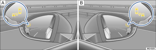 Fig. 182 In the outside mirrors: Indicator lights for the Blind Spot Monitor.Read and follow the introductory information and safety information first⇒Introduction to the subject
The Blind Spot Monitor uses sensors to monitor the blind spot detection area and the area behind your vehicle and informs you via indicator lights in the outside mirrors. The system measures the distance to other vehicles and the difference in speed between your vehicle and other vehicles. The Blind Spot Monitor only works at speeds above about 9 mph (15 km/h).
The Blind Spot Monitor automatically deactivates when driving through tight curves in the road. In this situation, the deactivation occurs without a driver information message. No warnings appear in the mirror glass or in the instrument cluster display. After driving through the curve, the Blind Spot Monitor automatically reactivates and the system is available again.
The indicator light ⇒ Fig. 182 in the glass for the respective outside mirror informs you about traffic to the rear, if the system interprets the situation as critical. The indicator light in the driver side outside mirror informs you about traffic to the left, and the indicator light in the passenger side outside mirror
informs you about traffic to the right of your vehicle.
Tinting on the side windows or aftermarket tinting films can interfere with the indicator lights in the outside mirrors or cause false readings.
Keep the glass in the outside mirrors clean and free of snow and ice, and do not cover the mirrors with stickers or other objects.
The radar sensors are behind the rear bumper on the left and right ⇒ Fig. 3 . They are not visible from outside the vehicle. They monitor an area about 21 yards (20 meters) behind the vehicle as well as the blind spots on the left and right sides of the vehicle. The monitored area next to the vehicle is about one lane wide.
The width of the lane is not detected individually on each road, but is preprogrammed into the system. Because of this, the indicators may be incorrect when driving on narrow roads or driving in the center of two lanes. Likewise, vehicles that are two lanes away from you or stationary objects such as guard rails may also be detected and cause a false warning.
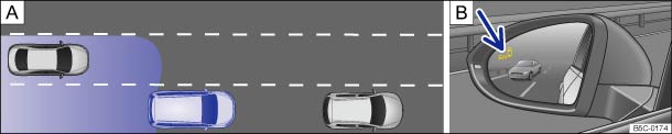 Fig. 183 : Driving situation when passing with traffic behind your vehicle. : Blind Spot Monitor indicator light in the driver side mirror.
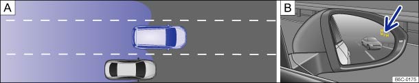 Fig. 184 : Driving situation when passing and merging into the lane. : Blind Spot Monitor indicator light in the passenger side mirror.Read and follow the introductory information and safety information first⇒Introduction to the subject
The following situations result in a signal in the outside mirror ⇒ Fig. 183 (arrow) or ⇒ Fig. 184
(arrow):
The faster another vehicle approaches, the earlier the signal in the outside mirror appears, because the Blind Spot Monitor accounts for the difference in speed between your vehicle and other vehicles. Therefore, the signals may trigger for different vehicles at different times, even when the distance to those vehicles is the same.
The Blind Spot Monitor only works at speeds above about 9 mph (15 km/h). The system switches off automatically when the vehicle speed drops below about 6 mph (10 km/h).
In certain situations, the Blind Spot Monitor may not interpret the traffic situation correctly. These situations may include:
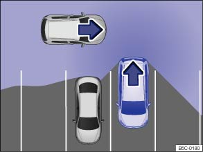 Fig. 185 Rear Traffic Alert: Monitored area around the vehicle that is backing out of a parking space.
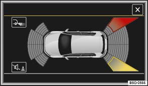 Fig. 186 Rear Traffic Alert display: Colored display shown (may vary depending on vehicle equipment).Read and follow the introductory information and safety information first⇒Introduction to the subject
| Key to ⇒ Fig. 186 | |
|---|---|
| Color or symbol | Meaning |
|
|
The yellow area indicates that the system has possibly detected traffic behind the vehicle. |
|
|
The red area indicates that the system has detected traffic behind the vehicle. |
|
|
There is a system malfunction in the scanned area (not pictured). |
The Rear Traffic Alert system uses the radar sensors in the rear bumper to monitor the traffic crossing behind your vehicle when you are backing out of a parking space or maneuvering, for example, in traffic situations with poor visibility.
A warning sounds if the system detects approaching traffic behind your vehicle when backing up ⇒ Fig. 185 (red area).
If the Rear Traffic Alert detects an approaching vehicle and the driver does not press the brake pedal, the system can intervene with automatic braking.
The Rear Traffic Alert assists the driver with harsh automatic braking that could help prevent or reduce damage that may result from a collision. The automatic braking occurs while backing up at speeds between 1–7 mph (1–12 km/h). Once the system detects that your vehicle is stationary, it keeps the vehicle from moving for up to 2 seconds.
After an automatic braking intervention, about 10 seconds must pass before the system can brake automatically again.
The driver can interrupt the automatic braking and take control of the vehicle by pressing firmly on the gas or brake pedal.
WarningThe Blind Spot Monitor with Rear Traffic Alert technology cannot overcome the laws of physics and limits of the system. Careless or unintentional use of the Blind Spot Monitor and Rear Traffic Alert may result in accidents and serious injuries.
Read and follow the introductory information and safety information first⇒Introduction to the subject
On appropriately equipped vehicles, you can turn the Blind Spot Monitor and Rear Traffic Alert on and off in the Assist systems menu in the Volkswagen Information System.
Open the Assist systems menu.
When the box next to the option is checked , the function will turn on automatically when the ignition is switched on.
The indicator lights in the outside mirrors will turn on briefly to confirm that the Blind Spot Monitor is ready.
The indicator light in the instrument cluster informs you about the status of the system.
The last system setting that was stored is kept after switching the ignition off/on.
If the Blind Spot Monitor was deactivated automatically, the system can only be activated again after switching the ignition off/on.
The radar sensors for the Blind Spot Monitor with Rear Traffic Alert turn off automatically if the system detects a permanent obstruction over a radar sensor. This could occur if the radar sensor area is covered by ice or snow, for example.
A text message appears in the instrument cluster display when the system turns off automatically.
When towing a trailer, the Blind Spot Monitor and Rear Traffic Alert must be manually switched off.
Introduction to the subjectIn this chapter you will find information on the following subjects:⇒ Indicator light ⇒ Function and operation ⇒ Adjusting the Custom driving mode
Your vehicle may be equipped with the Driving Mode Selection feature.
WarningDriving on today's roads demands the full attention of the driver at all times. Driver distraction causes accidents, collisions and serious personal injury!
Read and follow the introductory information and safety information first⇒Introduction to the subject
| Lights up |
Possible cause ⇒
|
|---|---|
|
|
Dynamic Chassis Control (DCC) system malfunction (if equipped). Have the system checked by an authorized Volkswagen dealer or authorized Volkswagen Service Facility. |
When the ignition is switched on, several warning and indicator lights come on briefly for a function check. They go out after a few seconds.
WarningFailure to heed warning and indicator lights and instrument cluster text messages can result in a collision and serious personal injury.
NoteFailure to heed warning and indicator lights or text WARNINGS can result in vehicle damage.
Displayed in color on an instrument cluster with color display.
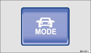 Fig. 187 In the lower center console: Driving Mode Selection button.Read and follow the introductory information and safety information first⇒Introduction to the subject
The driver can choose from different driving modes with a variety of characteristics:
| Driving mode | Recommended driving situations |
|---|---|
| Comfort | Gives the vehicle a more comfortable driving feel, which may be preferred, for example, on bumpy road conditions or on long highway drives. |
| Normal | Balanced setting for everyday use. |
| Sport | Gives the vehicle a sporty driving feel and is suited for a sporty driving style. |
| Race | |
| Custom | Individual systems can be adjusted to suit your personal requirements ⇒ Adjusting the Custom driving mode . |
The effect on the vehicle settings in the individual driving modes depends on vehicle equipment.
The driving mode can be changed while the vehicle is stationary or when it is moving. After selecting a driving mode, the vehicle settings (excluding engine settings) are switched to the new driving mode immediately.
When traffic conditions allow, briefly take your foot off the accelerator to activate the newly selected driving mode for the engine.
In Sport or Race mode, power steering is reduced and the effort required to steer the vehicle increases. The vehicle's driving response becomes more agile.
The engine and transmission will give either a more dynamic or more balanced response to the movement of the accelerator, depending on the selected driving mode. In vehicles with an automatic transmission, the shift points and the coasting mode will also change. Active cruise control can affect the acceleration response.
When the ACC is active, vehicle acceleration and deceleration can become more sporty, depending on the selected driving mode.
AFS and Light Assist give either a more dynamic or more balanced response to the current driving situation, depending on the selected driving mode.
While driving, DCC continuously adjusts the suspension characteristics to match the current road and driving conditions in accordance with the selected driving mode.
If the DCC system malfunctions, the indicator light appears in the instrument cluster display along with a driver information message.
The engine sound can be adjusted in the Custom driving mode.
In the Sport driving mode, the front differential lock provides a more agile driving response.
The selected driving mode will stay set even after the ignition has been switched off.
If the Sport, Race, or Custom modes are selected, the lights up. The light in the button goes out when the Normal driving mode is selected.
In vehicles with an automatic transmission, the transmission automatically shifts to Sport drive (S) when either the Sport or Race driving mode is selected. After the ignition is switched off, the current driving mode remains set but the automatic transmission may return to Drive (D) when the ignition is switched back on again.
To shift to Sport drive (S), briefly pull the selector lever back ⇒ Shifting .
WarningChanging the driving mode can alter the vehicle handling. Never allow Driving Mode Selection to tempt you into taking extra risks.
WarningFailure to heed warning lights and instrument cluster text messages can cause the vehicle to break down in traffic and result in a collision and serious personal injury.
NoteFailure to heed warning lights or text WARNINGS can result in vehicle damage.The driver can adjust certain vehicle functions, regardless of the selected driving mode. For example, the driver can shift the selector lever to Sport drive (S), even if the Normal driving mode is selected.
Available only on models equipped with Dynamic Chassis Control (DCC).
Available only on Golf R models (instead of Sport mode).
Read and follow the introductory information and safety information first⇒Introduction to the subject
The systems that can be adjusted to your individual requirements depend on the vehicle equipment.
A checkmark next to the name of the function indicates that the function is switched on.
Tapping the function key always takes you back to the previously active menu.
The following options in the Custom menu may vary depending on vehicle equipment.
| Submenu | Settings options |
|---|---|
| DCC: | Comfort |
| Normal | |
| Sport | |
| Steering: | Normal |
| Sport | |
| Drive system: | Normal |
| Sport | |
| Front differential lock: | Normal |
| Sport | |
| ACC: | Normal |
| Sport | |
| Dyn. Adapt. Frnt. Lght (AFS) | Normal |
| Sport | |
| Engine sound: | Normal |
| Sport | |
| Reset mode: | Settings are reset to Normal. |
Changes to the settings are applied immediately, with the exception of engine settings.
WarningDriving on today's roads demands the full attention of the driver at all times. Driver distraction causes accidents, collisions and serious personal injury!
Option only available on models equipped with Dynamic Chassis Control (DCC).
Option only available on models equipped with Adaptive Cruise Control (ACC).
Introduction to the subjectIn this chapter you will find information on the following subjects:⇒ Performance Monitor sport gauges ⇒ Performance Monitor lap timer and stopwatch
Your vehicle may be equipped with the Performance Monitor feature.
WarningDriving on today's roads demands the full attention of the driver at all times. Driver distraction causes accidents, collisions and serious personal injury!
WarningRapid acceleration can cause skidding and loss of traction, especially on slippery roads, resulting in a loss of vehicle control, collisions, and serious personal injury.
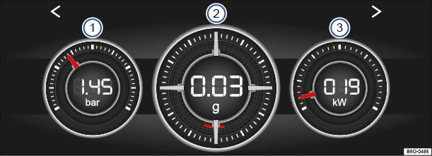 Fig. 188 In the Infotainment system: Performance Monitor sport gauges. Gauges shown in the display may vary depending on configuration.Read and follow the introductory information and safety information first⇒Introduction to the subject
Your vehicle may be equipped with the Performance Monitor feature, which includes sport gauges and a lap timer/stopwatch in the Infotainment system.
Depending on vehicle equipment, the following Performance Monitor sport gauges may be available:
You can access the Performance Monitor sport gauges in the Infotainment system by pressing the button followed by Selection and Sport.
Tap the arrow buttons at either side of the screen to toggle between the Performance Monitor sport gauges and the lap timer/stopwatch ⇒ Performance Monitor lap timer and stopwatch .
The display can show 3 Performance Monitor sport gauges at any given time. Swipe your finger up or down on a gauge to select a different one.
For some gauges, the units can be changed in the Infotainment system. See ⇒ Menu and system settings .
The boost pressure gauge ⇒ Fig. 188① shows the pressure in the boost pressure duct between the turbocharger and the engine (shown in bar or psi, depending on the units selected). The farther right the needle points on the gauge, the higher the pressure in the boost pressure duct and the greater the output from the engine.
The accelerometer, or g-meter ⇒ Fig. 188② , shows the current vehicle acceleration in the center display (shown in g).
The red mark moves to different areas of the gauge as the direction of acceleration changes. If you turn left, the mark moves to the right of the gauge (and vice versa). The red mark also moves down when accelerating and up when braking. These values are combined in certain situations, for example, when making a right turn while accelerating, the red mark moves to the lower left area of the gauge.
The red mark also moves toward or away from the center of the gauge depending on the level of acceleration. The farther the red mark is from the center, the heavier the acceleration (greater g).
The power display ⇒ Fig. 188③ shows the current engine power output on both a gauge and a digital display (shown in kilowatts).
If the needle in the engine oil temperature gauge is located in the cold range, the engine has not reached operating temperature. Avoid high engine speeds and heavy engine loads until the engine has reached operating temperature.
The engine has reached operating temperature when the needle moves into the center of the gauge under normal driving conditions. The needle may move farther to the right on the gauge with a heavier engine load at high outside temperatures. This is not a cause for concern as long as the indicator light does not light up or flash in the instrument cluster See ⇒ Engine oil .
If the needle in the engine coolant temperature gauge is located in the cold range, the engine has not reached operating temperature. Avoid high engine speeds and heavy engine loads until the engine has reached operating temperature.
Under normal driving conditions, the needle should be in the middle of the gauge. The temperature may go higher when the engine is working hard, especially in hot weather. This is not a cause for concern as long as the indicator light does not light up or flash in the instrument cluster. See ⇒ Engine coolant .
WarningDriving on today's roads demands the full attention of the driver at all times. Driver distraction causes accidents, collisions and serious personal injury!
WarningRapid acceleration can cause skidding and loss of traction, especially on slippery roads, resulting in a loss of vehicle control, collisions, and serious personal injury.NoteTo help prevent engine damage, always avoid high engine speeds, full throttle acceleration and heavy engine loads when the engine is cold.Because conditions used to determine vehicle performance may vary, the displayed values may not always be exact.
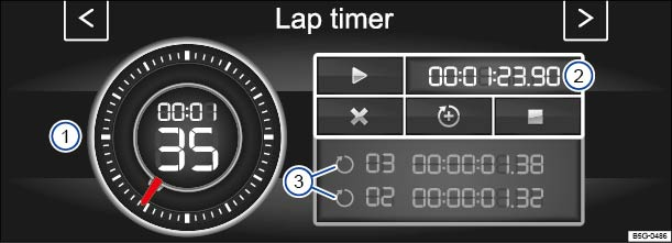 Fig. 189 In the Infotainment system: Performance Monitor lap timer/stopwatch.
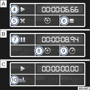 Fig. 190 In the Infotainment system: Buttons for operating the Performance Monitor lap timer/stopwatch. The buttons displayed vary depending on the current lap timer/stopwatch activity.Read and follow the introductory information and safety information first⇒Introduction to the subject
You can access the lap timer/stopwatch in the Infotainment system by pressing the button followed by the Selection and Sport function keys.
Tap the arrow buttons at either side of the screen to toggle between the Performance Monitor sport gauges and the lap timer/stopwatch ⇒ Performance Monitor sport gauges .
Key to ⇒ Fig. 189 and ⇒ Fig. 190 :
Stopwatch displayDigital split time displayDisplay of recent split timesPlay button to start timingButton to cancel the current lapStop button to end timingPause button to pause timingButton to start a new lapButton to show lap split times in the stopwatch displayButton to show statisticsThe stopwatch has two different measuring functions. The stopwatch in the outer ring of the display (red needle) ⇒ Fig. 189① can measure up to 60 seconds. The digital display in the center of the stopwatch shows the elapsed hours, minutes, and seconds. The seconds appear as large numbers.
The digital display on the right side ⇒ Fig. 189② shows the current lap split time in 1/100 second intervals. If the lap timer is not being used to track split times, both digital displays show the same time.
| Function | Action ⇒ Fig. 189 and ⇒ Fig. 190 |
|---|---|
| Start or resume timing: |
Tap the play button If you tap the play button when the vehicle is not moving, a confirmation message appears in the display. Tap Start to begin timing immediately. Otherwise, the timer starts automatically as soon as the vehicle moves forward. If laps have already been completed and are recorded in the statistics, timing will resume on the current lap. A new first lap can only be started if the statistics are reset in the statistics area. Tap the statistics button |
| Stop timing: |
Tap the stop button |
| Pause timing: |
Tap the pause button |
| Start a new lap: |
Tap button Timing of the current lap is interrupted and a new lap begins. The time of the completed lap is carried over to the statistics. |
| Cancel the current lap: |
Tap button Timing of the active lap ends and the lap time is deleted. It is entered in the statistics as --:--:--:--. |
| Show lap split times in the stopwatch display: |
Tap button The split time is shown in the digital display in the center of the stopwatch ⇒ Fig. 189① only. |
| Show lap statistics: |
Tap the statistics button From this screen you can also reset stored lap times. |
| Reset lap timer and statistics: | Tap the Reset button in the statistics area (not shown). |
A maximum of 99 laps and a maximum overall duration of 99 hours, 59 minutes, and 59 seconds can be recorded. If one of the two limits is reached, timing can only start again after tapping the Reset button in the statistics area.
For vehicles equipped with a lap timer in the instrument cluster display, see ⇒ Volkswagen Information System .
WarningDriving on today's roads demands the full attention of the driver at all times. Driver distraction causes accidents, collisions and serious personal injury!
WarningRapid acceleration can cause skidding and loss of traction, especially on slippery roads, resulting in a loss of vehicle control, collisions, and serious personal injury.
NoteTo help prevent engine damage, always avoid high engine speeds, full throttle acceleration, and heavy engine loads when the engine is cold.
Introduction to the subjectIn this chapter you will find information on the following subjects:⇒ Manual controls ⇒ Climatronic controls ⇒ Operation via the Infotainment system ⇒ Operation ⇒ Air vents ⇒ Air recirculation
Your vehicle is equipped with either a manual air conditioning climate control system or a Climatronic climate control system.
On vehicles with Climatronic climate control, Climatronic information appears in the Climatronic display and/or on the screen of the factory-installed Infotainment system.
The dust and pollen filter reduces the entry of pollutants into the passenger compartment.
The dust and pollen filter must be replaced at the intervals recommended in ⇒BookletWarranty and Maintenance, so that the air conditioner can work properly.
If the effectiveness of the filter decreases prematurely due to operating the vehicle where the outside air is heavily polluted, the dust and pollen filter should be replaced more frequently than indicated.
WarningPoor visibility increases the risk of collisions and other accidents that cause serious personal injuries.
WarningStale air causes driver fatigue and reduces driver alertness, which can cause accidents, collisions and serious personal injury.
Note
If the air conditioner is switched off, the fresh outside air will not be dehumidified. To help keep the windows from fogging over, Volkswagen recommends leaving the air conditioner (compressor) switched on. Press the button. The indicator light in the button must light up.
When it is very hot and humid outside, water condensation can drip from the air conditioner evaporator and form a puddle under the vehicle. This is normal and does not indicate a leak.Keep the air intake slots in front of the windshield free of ice, snow, and leaves in order to maintain proper functioning of the heating and ventilation systems.Maximum heating output and defrosting performance are not possible until the engine has reached operating temperature.Emergency starting and starting the engine with a very weak vehicle battery or after the vehicle battery has been replaced may change or delete system settings (including time, date, personal convenience settings, and programming). Check the settings and correct as necessary once the vehicle battery has built up a sufficient charge.
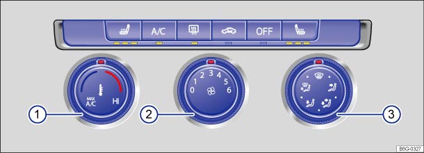 Fig. 191 In the center console: Manual air conditioning controls.Read and follow the introductory information and safety information first⇒Introduction to the subject
Press the corresponding button to switch a function on or off. If a function is switched on, an indicator light under the button lights up. To switch off a function, press the button again.
| Button/Knob | More information: Manual air conditioning ⇒ Fig. 191 |
|---|---|
|
Temperature ① |
Turn knob to set the desired temperature. The |
|
Fan ② |
Setting 0: the fan and manual air conditioning are switched off. Setting 6: highest fan speed. |
| Air distribution ③ | Direct airflow by turning knob to any setting (continuously adjustable). |
|
|
Defog/defrost: Airflow is directed to the windshield. Recirculation mode switches off automatically in this position. Increases the fan speed to clear the windshield as quickly as possible. The cooling system switches on automatically to dehumidify the air. |
|
|
Air distribution to the upper instrument panel outlets. |
|
|
Air distribution to the upper instrument panel outlets and footwells. |
|
|
Air distribution to the footwells. |
|
|
Air distribution to the windshield and footwells. |
|
|
Rear window defroster: Works only when the engine is running and switches off automatically after 10 minutes or less. |
|
|
Air recirculation mode ⇒ Air recirculation . |
|
|
Buttons for seat heating (if equipped) ⇒ Seat heating . |
|
|
Press the button to switch the air conditioner on or off. |
|
|
Press the |
WarningStale air causes driver fatigue and reduces alertness, which can cause accidents, collisions, and serious personal injury.
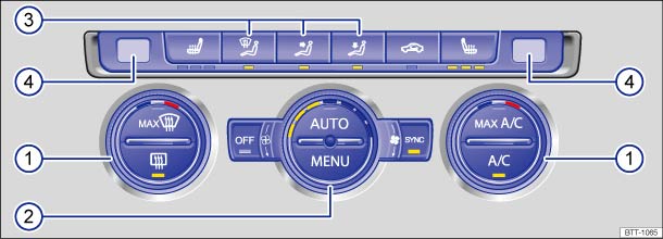 Fig. 192 In the center console: Climatronic controls.Read and follow the introductory information and safety information first⇒Introduction to the subject
Press the corresponding button to switch a function on or off. If a function is switched on, an indicator light in or under the button lights up. To switch off a function, press the button again.
| Button/Knob | More information: Climatronic ⇒ Fig. 192 . |
|---|---|
|
Temperature ① |
Left and right sides of the vehicle can be set to different temperatures. Turn the knob to set the temperature. |
|
Fan ② |
The fan speed is automatically controlled depending on the vehicle speed in order to help prevent unnecessary noise. The fan can also be adjusted manually. |
| Air distribution ③ | Air flow is automatically adjusted to a comfortable level. It can also be manually adjusted with buttons ⇒ Fig. 192③ . |
| Displays ④ | Left-side and right-side digital temperature displays. |
|
|
Defog/defrost button. The incoming outside air is directed to the windshield, and air recirculation automatically switches off. To defrost the windshield as quickly as possible, humidity is removed from the air at temperatures above about +35 °F (+1.5 °C), and the blower is set to a high speed. |
|
|
Air distribution to the upper instrument panel outlets. |
|
|
Air distribution to the footwells. |
|
|
Air is directed upward. |
|
|
Rear window defroster: Works only when the engine is running and switches off automatically after 10 minutes or less. |
|
|
Manual and automatic air recirculation ⇒ Air recirculation . |
|
|
Buttons for seat heating ⇒ Seat functions . |
|
|
Press the button to switch the air conditioner on or off. |
|
|
Press the button for maximum air conditioner cooling. The air recirculation and cooling system are switched on automatically and the air distribution is automatically set to position |
|
|
Applies the temperature settings for the driver side to the passenger side: If the indicator light in the Press the button or turn the temperature knob for the passenger side to set a different temperature for the passenger side. The indicator light in the button goes out. |
|
|
Automatic temperature control, fan speed, and air distribution. Press the |
|
|
Press the button to open the air conditioning settings in the Infotainment system ⇒ Operation via the Infotainment system . |
|
|
Press the OR: Turn the blower switch to the left as far as it will go. OR: Switch off using the Infotainment system ⇒ Operation via the Infotainment system . |
WarningStale air causes driver fatigue and reduces alertness, which can cause accidents, collisions, and serious personal injury.
When adjusting fan speed manually, LEDs in the knob ⇒ Fig. 192② light up to indicate the current fan speed. During automatic regulation, the fan speed is not indicated.
Read and follow the introductory information and safety information first⇒Introduction to the subject
For vehicles equipped with the Climatronic climate control system, various settings can also be adjusted via the Infotainment system.
The current air conditioning settings are displayed in the upper section of the screen, for example, the temperatures that are currently set for the driver and passenger sides. Blue arrows indicate that cool air is flowing from the vents, while red arrows indicate that warm air is flowing from the vents.
Tap the corresponding function key to switch a function on or off, or to select a submenu.
The following menu items may be available, depending on vehicle equipment.
| Function key | Options |
|---|---|
|
|
Tap the function key for automatic temperature control, fan speed, and air distribution. The indicator light in the |
|
|
Tap the function key for maximum air conditioner cooling. The air recirculation and cooling system are switched on automatically and the air distribution is automatically set to position |
|
|
Tap the function key for defog/defrost. The incoming outside air is directed to the windshield, and air recirculation automatically switches off. To defrost the windshield as quickly as possible, humidity is removed from the air at temperatures above about +35 °F (+1.5 °C), and the blower is set to a high speed. |
|
|
Displays only when the climate control system is in manual mode. |
| Temperature displays for driver side and passenger side |
Tap the blue bar at the left of each function key to decrease the temperature. Tap the red bar at the right of each function key to increase the temperature. |
|
|
Tap to switch the Climatronic on (white) or off (yellow). |
|
|
Applies the temperature settings for the driver side to the passenger side. The word |
|
Settings |
Open the submenu for climate control settings. The following settings can be made: |
| Tap the Automatic air recirculation function key to switch automatic air recirculation on and off. | |
|
Tap the function key |
Read and follow the introductory information and safety information first⇒Introduction to the subject
The air conditioner works only when the ignition is switched on. The cooling system for the passenger compartment works only when the engine is running and the fan is on.
The air conditioner is most efficient when the windows and the power sunroof are closed. If the vehicle is stationary and the passenger compartment becomes very hot due to sunlight, briefly opening the windows and the power sunroof may speed up the cooling process.
Keep the air intake slots in front of the windshield free of ice, snow, and leaves so that the heating and ventilation systems can work properly.
When you switch on the cooling system, both the temperature and humidity in the vehicle are reduced. This will help make passengers feel more comfortable and help keep the windows from fogging up.
For manual air conditioning
For Climatronic
The inside and outside temperatures can be displayed in either Fahrenheit (F) or Celsius (C).
On appropriately equipped vehicles, you can change the units in the Infotainment system by pressing the button followed by the
and Units function keys ⇒ Menu and system settings .
Maximum heating output and defrosting performance are not possible until the engine has reached operating temperature.
The air conditioner may not switch on for one of the following reasons:
When it is very hot and humid outside, water condensation can drip from the air conditioner evaporator and form a puddle under the vehicle. This is normal and does not indicate a leak.
The climate control system adjusts the passenger compartment temperature as fast as possible considering the outside temperature.Due to residual moisture in the air conditioner, the windshield may fog up after the engine is started. Switch on the windshield defroster to help evaporate the condensation as quickly as possible.The air coming out of the vents flows through the passenger compartment and through the vents in the luggage compartment. Do not cover these slots with clothing or other things.
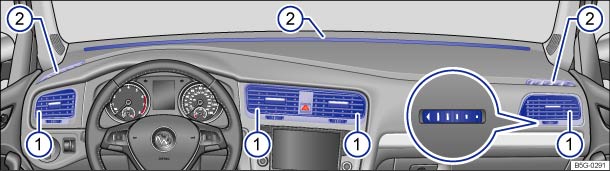 Fig. 193 In the instrument panel: Air vents.Read and follow the introductory information and safety information first⇒Introduction to the subject
To help ensure sufficient heating, cooling, and ventilation in the passenger compartment, never close the air vents completely ⇒ Fig. 193① .
Additional, non-adjustable air vents are located in the instrument panel ⇒ Fig. 193② , in the footwells, as well as in the rear area of the passenger compartment.
Some models also have an adjustable air vent inside the glove compartment ⇒ Glove compartment .
NoteDo not place food, medications, or other temperature-sensitive things in front of the air vents. Food, medications, and other things that are sensitive to heat or cold can be damaged or made unusable by the air flow from the vents.The air coming out of the vents flows through the passenger compartment and through the air vents in the luggage compartment. Do not cover these slots with clothing or other things.
Read and follow the introductory information and safety information first⇒Introduction to the subject
There are different types of air recirculation:
|
|
Manual air recirculation. |
| Automatic air recirculation mode (Climatronic only). | |
The air recirculation mode helps prevent outside air from entering the vehicle interior.
In very hot outside temperatures, temporarily switch to manual air recirculation in order to cool the vehicle interior faster.
For safety reasons, air recirculation is switched off in the following situations ⇒ .
Switching on: Press the button. The indicator light under the button lights up.
Switching off: Press the button. The indicator light under the button goes out.
If the box in the function key is checked , the automatic recirculation mode is switched on.
In automatic air recirculation mode, fresh air enters the passenger compartment. If the system detects an increased concentration of pollutants in the outside air, it automatically switches to air recirculation. As soon as the pollutant level is back in the normal range, air recirculation is switched off.
Unpleasant odors cannot be detected by the system.
To prevent condensation from forming on the windows, air recirculation does not automatically switch on in certain situations.
WarningStale air causes driver fatigue and reduces driver alertness, which can cause accidents, collisions and serious personal injury.
NoteDo not smoke when air recirculation is switched on. Smoke drawn into the ventilation system can leave residue on the evaporator and on the dust and pollen filter, resulting in permanent odors whenever the air conditioner is switched on.Climatronic: When backing up and while the automatic wiper/washer is operating, air recirculation is briefly activated to help keep exhaust fumes from getting into the passenger compartment.
Introduction to the subjectIn this chapter you will find information on the following subjects:⇒ Indicator lights and fuel gauge ⇒ Refueling ⇒ Fuel capacities ⇒ Refueling checklist
The fuel filler flap is located on the rear right side of the vehicle.
WarningImproper refueling or handling of fuel is dangerous and can cause fire, explosion, and severe burns.
WarningEven if empty, portable fuel containers can leak and cause a fire and serious personal injuries, especially in a crash.
Note
Fuels can pollute the environment. Spilled fuel must be collected and disposed of properly, following all applicable environmental regulations.There is no emergency release for the fuel filler flap. Contact an authorized Volkswagen dealer or an authorized Volkswagen Service Facility for assistance.
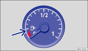 Fig. 194 In the instrument cluster: Fuel gauge.Read and follow the introductory information and safety information first⇒Introduction to the subject
| Lights up |
Gauge position ⇒ Fig. 194 |
Possible cause or meaning ⇒
|
Proper response |
|---|---|---|---|
|
|
Red range (arrow) |
Fuel tank almost empty. Running on reserve ⇒ Fuel capacities . |
Time to refuel ⇒ .
|
|
|
– | Fuel filler cap not properly closed. | Stop and close the fuel filler cap properly. |
When the ignition is switched on, several warning and indicator lights come on briefly for a function check. They go out after a few seconds.
If the indicator light comes on or you see a text message in the instrument cluster display indicating that the fuel filler cap is not properly closed, stop the vehicle in a safe place and switch off the engine and the ignition.
Open the fuel filler flap and take the fuel filler cap off the filler neck. Then put the fuel filler cap back on the filler neck and screw it on clockwise until you clearly hear a clicking sound. Close the fuel filler flap.
After switching on the ignition, the indicator light may stay on or the text message may still appear in the instrument cluster display, even if the fuel filler cap is now properly closed. This is normal and no reason to take your vehicle in for service.
If, however, the malfunction indicator light also comes on, drive to your nearest authorized Volkswagen dealer or authorized Volkswagen Service Facility and have the fuel system and the engine checked.
WarningDriving with a fuel tank that is almost empty can lead to stalling in traffic, a collision, and serious personal injuries.
Note
The small arrow next to the gas pump symbol in the fuel gauge ⇒ Fig. 194 shows the side of the vehicle with the fuel filler flap.
Displayed in color on an instrument cluster with color display.
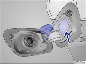 Fig. 195 Right rear side of vehicle: Fuel cap placed on the open fuel filler flap.Read and follow the introductory information and safety information first⇒Introduction to the subject
Before refueling, always switch off the engine, the ignition, and all mobile phones, and leave them switched off until refueling is complete.
The correct fuel grade for your vehicle ⇒ Fuel is listed on a sticker on the inside of the fuel filler flap ⇒ Fig. 195 (arrow).
.WarningSpilled fuel can cause fires, explosions, burns, and other severe injuries.
NoteRemove fuel spills from all vehicle surfaces immediately to help prevent damage to the paint, tires, and wheel housings.Fuel spills may pollute the environment.
Read and follow the introductory information and safety information first⇒Introduction to the subject
| Model | Fuel tank capacity |
|---|---|
| Golf, Golf GTI |
About 13.2 gallons (50.0 liters), of which about 1.3 gallons (5.0 liters) are reserve. |
| Golf R |
About 14.5 gallons (55.0 liters), of which about 1.3 gallons (5.0 liters) are reserve. |
Read and follow the introductory information and safety information first⇒Introduction to the subject
The engine compartment of any motor vehicle is a hazardous area. Never do any work on the engine or in the engine compartment unless you
Windshield washer fluid level Windshield wipers and washer
Engine oil level Engine oil
Engine coolant level Engine coolant
Brake fluid level Braking and parking
Tire pressure Tires and wheels
Information on replacing light bulbs: ⇒ Replacing light bulbs .
WarningDisregarding the safety-related checklist may lead to accidents and injuries.
Introduction to the subjectIn this chapter you will find information on the following subjects:⇒ Gasoline ⇒ Gasoline additives
The correct fuel grade for your engine is shown on a sticker located on the inside of the fuel filler flap ⇒ Fig. 195 .
Bad or poor quality fuel reduces operating performance, efficiency and service life of the engine. If you notice any symptoms like rough engine idle or performance, bucking, or if an indicator light comes on ⇒ Indicator lights and fuel gauge , immediately reduce the vehicle speed, accelerate slowly, and keep the engine speed in the middle of the rpm range. Avoid high rpm and rapid acceleration. If these symptoms should appear right after refueling, switch off the engine. In both cases contact an authorized Volkswagen dealer or an authorized Volkswagen Service Facility to have the engine checked.
WarningImproper refueling or handling of fuel can cause fire, explosion, and severe burns.
Read and follow the introductory information and safety information first⇒Introduction to the subject
Octane rating indicates a gasoline's ability to resist engine-damaging “knock” caused by pre-ignition. Using gasoline that does not meet minimum octane requirements can affect engine performance, while the use of poor quality gasoline or gasoline with octane levels below 87 can also cause engine damage. If Regular gasoline is recommended for your engine, you may be able to enhance engine performance by using Premium gasoline.
The recommended gasoline octane rating for your engine is listed on a label inside of the fuel filler flap. This rating may be specified according to AKI (CLC) or RON (ROZ) standards.
Regardless of whether unleaded Regular or Premium grade gasoline is specified for your vehicle, Volkswagen recommends using TOP TIER Detergent Gasoline with a minimum octane rating of 87 AKI (91 RON) for Regular gasoline, and 91 AKI (95 RON) for Premium gasoline. For more information on TOP TIER Detergent Gasoline, please go to the official website, http://www.toptiergas.com.
The gasoline grades most commonly sold in the United States and Canada have the following octane ratings, which can usually be found on the filler pump:
Unleaded gasoline is available throughout the USA and Canada. Volkswagen recommends that you do not take your vehicle to places where unleaded gasoline may not be available.
You may use unleaded gasoline blended with alcohol or MTBE (methyl tertiary butyl ether), commonly referred to as oxygenated fuels, if the blended mixture meets the following criteria:
Blends of gasoline and methanol (wood alcohol or methyl alcohol):
Blends of gasoline and ethanol (grain alcohol or ethyl alcohol):
Blends of gasoline and MTBE:
Many fuels are blended especially for winter or summer conditions. When seasons change, Volkswagen suggests that you buy fuel at busy stations where the seasonal adjustment is more likely to be made earlier.
WarningStarting fluids can explode and cause a run-away vehicle condition.
Note
Even a single tank full of leaded fuel can do major damage to the catalytic converter and degrade its effectiveness in reducing polluting emissions.If you notice a loss of fuel economy or drivability and performance problems using one of these fuel blends, we recommend that you switch to unblended fuel. Never use fuel line antifreeze offered for gasoline engines.
Read and follow the introductory information and safety information first⇒Introduction to the subject
Additives are used to improve the quality of the gasoline.
Fuel quality impacts the operating performance, efficiency and service life of the engine. Therefore, use high quality gasoline that is already blended by the fuel supplier with suitable gasoline additives that do not contain metal. The additives provide corrosion protection, clean the fuel system, and help prevent deposits on the engine.
Volkswagen recommends TOP TIER Detergent Gasoline. For more information on TOP TIER Detergent Gasoline, please go to the official Web site http://www.toptiergas.com.
If quality gasoline with additives that do not contain metal is not available or engine malfunctions occur, you should add the required additives while refueling ⇒ .
Not all gasoline additives are effective. Using the wrong additives can cause significant and expensive damage to the engine and the catalytic converter. Never use additives that contain metal. Please note that metal can be included in some aftermarket gasoline additives that are available to be added to gasoline during or after refueling to help improve knock resistance or increase the octane rating.
Volkswagen recommends using only additives approved by Volkswagen. Appropriate additives as well as instructions on how to use them are available from your authorized Volkswagen dealer or authorized Volkswagen Service Facility. Do not add any other gasoline additives.
NoteYou can damage the engine by using incorrect additives.
Introduction to the subjectIn this chapter you will find information on the following subjects:⇒ Display ⇒ Preparing to work in the engine compartment ⇒ Opening or closing the engine compartment
Always position the vehicle on a firm and level surface before doing any work in the engine compartment.
The engine compartment of a vehicle is a hazardous area. Never do any work on the engine or in the engine compartment unless you
.If you are uncertain in any way, have the work done by an authorized Volkswagen dealer or an authorized Volkswagen Service Facility. Serious personal injury may result from improperly performed work.
WarningUnintended vehicle movement during maintenance work can cause serious personal injuries.
WarningThe engine compartment of any motor vehicle is a potentially dangerous area and can cause serious personal injury.
WarningHigh voltage systems in the engine compartment can cause electrical shocks or even electrocution, severe burns, other serious injuries, and even death!
WarningMoving parts in the engine compartment can cause serious personal injury on contact.
WarningAdditional materials in the engine compartment such as blankets can interfere with the operation of the engine and can cause fires, which can lead to serious injuries.
WarningOperating fluids and some materials in the engine compartment can catch fire easily, causing burns and other serious personal injuries!
NoteWhen changing or topping off fluids, make sure that you pour the fluids into the correct reservoirs. Adding the wrong type of operating fluids will cause serious malfunctions and engine damage.Fluid leaks and spills are harmful to the environment. Regularly check the ground underneath your vehicle for this reason. If you find spots of oil or other fluids, have your vehicle checked by your authorized Volkswagen dealer or authorized Volkswagen Service Facility. Dispose of leaked operating fluids properly.
Read and follow the introductory information and safety information first⇒Introduction to the subject
| Lights up | Proper response |
|---|---|
| Icon appears in the display ⇒ Displays |
Engine hood not properly closed. Close the engine hood. |
When the ignition is switched on, several warning and indicator lights come on briefly for a function check. They go out after a few seconds.
If the engine hood is open or not closed properly, the vehicle icon appears in the instrument cluster display showing the open engine hood ⇒ Fig. 12 .
Depending on your vehicle's equipment and options, the icon may still be displayed even after the ignition is switched off as long as the key has not been taken out of the ignition. The instrument cluster display goes out about 15 seconds after the vehicle has been locked.
WarningFailure to heed warning lights and instrument cluster text messages can cause the vehicle to break down in traffic and result in a collision and serious personal injury.
Read and follow the introductory information and safety information first⇒Introduction to the subject
Park the vehicle in a safe place on a firm, level surface.
Hold the brake pedal down until the engine is switched off.
Set the parking brake to help prevent the vehicle from moving Parking brake (Golf, Golf GTI) or Electronic parking brake (Golf R) (depending on equipment).
Shift the transmission into Park (P) (automatic) or Neutral (manual only) Shifting.
Stop the engine and remove the key from the ignition switch or turn off the ignition with the starter button and remove the key from the vehicle Starting and stopping the engine.
Let the engine cool down sufficiently.
Keep children and others away from the vehicle.
Make sure the vehicle cannot move unexpectedly.
WarningDisregarding the safety-related checklist may result in serious injuries.
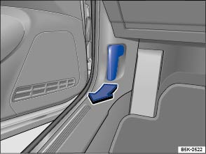 Fig. 196 In the footwell on the driver side: Inside engine hood release lever.
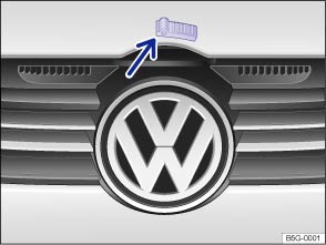 Fig. 197 Above the radiator grille: Outside engine hood release.Read and follow the introductory information and safety information first⇒Introduction to the subject
. . .If the hood does not close completely, open it again and close it properly.
When the hood is properly closed, you can see that it fits flush with the other body parts. The display in the instrument cluster no longer indicates that the engine hood is open ⇒ Display .
WarningIf the hood is not closed properly, it could fly up and block your view while you are driving. This can lead to a crash and serious personal injuries.
Note
NoteBefore opening or closing the engine hood, make sure there is enough room to do so, for example when the vehicle is in a garage.
Introduction to the subjectIn this chapter you will find information on the following subjects:⇒ Warning and indicator lights ⇒ Engine oil specifications ⇒ Engine oil capacities ⇒ Checking the engine oil level and adding oil ⇒ Engine oil consumption ⇒ Changing engine oil WarningImproper handling of engine oil can cause severe burns and other serious injuries.
Like all other operating fluids, engine oil can pollute the environment. Collect leaked or spilled operating fluids and dispose of them properly in accordance with applicable environmental laws and regulations.
Read and follow the introductory information and safety information first⇒Introduction to the subject
| Lights up | Possible cause | Proper response |
|---|---|---|
|
|
Engine oil level too low. |
Switch off the engine. Check the engine oil level ⇒ Checking the engine oil level and adding oil . If the engine oil level is too high, contact an authorized Volkswagen dealer or an authorized Volkswagen Service Facility for assistance ⇒ .
|
| Flashes | Possible cause | Proper response |
|---|---|---|
|
|
Engine oil pressure too low. |
Switch off the engine. Check the engine oil level ⇒ Checking the engine oil level and adding oil . – If the warning light flashes although the oil level is normal, do not continue driving or let the engine idle. Otherwise, the engine could be damaged. Contact an authorized Volkswagen dealer or an authorized Volkswagen Service Facility. |
|
|
Engine oil system malfunction. | Have the engine oil sensor checked by an authorized Volkswagen dealer or an authorized Volkswagen Service Facility. |
When the ignition is switched on, several warning and indicator lights come on briefly for a function check. They go out after a few seconds.
Depending on equipment, the engine oil temperature may be displayed in the Volkswagen Information System Driving data menu ⇒ Volkswagen Information System .
WarningFailure to heed warning lights and instrument cluster text messages can cause the vehicle to break down in traffic and result in a collision and serious personal injury.
NoteFailure to heed warning lights or text WARNINGS can result in vehicle damage.NoteDo not start the engine if the engine oil level is in range ⇒ Fig. 198Ⓐ . Contact an authorized Volkswagen dealer or an authorized Volkswagen Service Facility. Otherwise the catalytic converter and engine can be damaged!
Displayed in color on an instrument cluster with color display.
Read and follow the introductory information and safety information first⇒Introduction to the subject
The engine oil used must conform to exact specifications.
Using the proper engine oil is important for the functionality and service life of the engine. Your engine was factory-filled with a high-quality multi-grade oil which can usually be used throughout the entire year.
Engine oils are constantly being improved. Authorized Volkswagen dealers and authorized Volkswagen Service Facilities are always up-to-date regarding new developments and changes. Volkswagen therefore recommends that you have the engine oil changed by an authorized Volkswagen dealer or an authorized Volkswagen Service Facility.
Engine oil quality is based not only on requirements for engines and exhaust treatment systems, but also on fuel quality. Engine oil comes into contact with fuel and fuel residue in all internal combustion engines, causing engine oil to age and its lubricating qualities to deteriorate.
Your engine was factory-filled with a high-quality, synthetic all-season engine oil that meets strict Volkswagen oil quality standards and has a viscosity grade of SAE 5W-40. or SAE 5W-30. You can use this oil for normal driving in all temperatures.
If you need to add oil between oil changes, use only a high quality oil that expressly complies with the Volkswagen oil quality standard specified for your vehicle's engine:
| Engines | Engine oil specification |
|---|---|
| Gasoline engines |
VW 502 00 VW 503 00 VW 504 00 |
At the time this Manual was printed, the engine oils available in the U.S. that meet these Volkswagen standards are synthetic oils. This does not mean, however, that any synthetic engine oil will meet Volkswagen standards. Always use an approved oil that expressly complies with the Volkswagen oil quality standard that applies to your vehicle's engine.
If synthetic oil that meets the applicable Volkswagen oil quality standard with viscosity grade SAE 5W-40 or SAE 5W-30 is not available in your area, be sure to use a viscosity grade suitable for the climate, season, and operating conditions that exist where the vehicle is used. Make sure the oil meets the quality standard listed in .
Engine oils are constantly being improved. Authorized Volkswagen dealers and authorized Volkswagen Service Facilities are always up-to-date regarding new developments and changes. Volkswagen therefore recommends that you have the engine oil changed by an authorized Volkswagen dealer or an authorized Volkswagen Service Facility.
Note
Read and follow the introductory information and safety information first⇒Introduction to the subject
| Engines | Engine oil capacity (with filter) |
|---|---|
| 170 hp (125 kW), 1.8 L gasoline engines (Golf) | About 5.8 quarts (5.5 liters) |
| 210 hp (155 kW) 2.0 L gasoline engines (Golf GTI) | About 6.0 quarts (5.7 liters) |
| 220 hp (162 kW) 2.0 L gasoline engines (Golf GTI) | About 6.0 quarts (5.7 liters) |
| 292 hp (215 kW) 2.0 L gasoline engines (Golf R) | About 6.0 quarts (5.7 liters) |
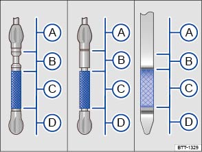 Fig. 198 Engine oil dipstick with oil level marks.
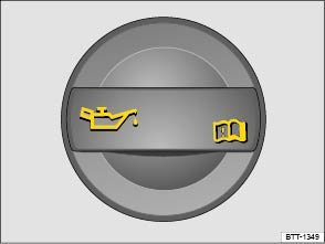 Fig. 199 In the engine compartment: Engine oil filler cap (cap design may vary depending on vehicle equipment).Read and follow the introductory information and safety information first⇒Introduction to the subject
With the engine at operating temperature, park the vehicle on a level surface to help prevent an incorrect oil level reading.
Switch off the engine and wait a few minutes for the engine oil to flow back into the oil pan.
Open the engine hood Working in the engine compartment.
Find the oil filler opening and the dipstick. You can identify these by the symbol on the engine oil filler cap and the colored handle on the dipstick. If you are not sure where the cap and the dipstick are located, see your authorized Volkswagen dealer or authorized Volkswagen Service Facility for assistance.
Remove the dipstick from the guide tube and wipe the dipstick off using a clean cloth.
Reinsert the dipstick into the guide tube and push it all the way in. If there is an alignment tab on the top of the engine oil dipstick, make sure it lines up with the notch in the guide tube, and that the dipstick goes all the way in.
After reading the oil level, reinsert the dipstick back into the guide tube and push it all the way in.
Remove the cap on the engine oil filler opening .
Only add engine oil that Volkswagen has approved for that engine. Add the oil gradually in small quantities (no more than 1 pint / 0.5 liter).
To help prevent overfilling, you must wait about 1 minute each time you add oil so that the oil can flow into the oil pan up to the marking on the dipstick.
Read the oil level on the dipstick again before adding another small amount, if necessary. Never add too much oil .
After adding oil, the level must at least be in the center of the Ⓒ range and can enter range Ⓑ, but should never enter range Ⓐ .
After adding oil, securely install the cap on the engine oil filler opening. Otherwise, oil could leak out while the engine is running.
Insert the oil dipstick back in the guide tube and push it all the way in.
Close the hood .
| ⇒ Fig. 198 | Required action according to the respective engine oil level: |
|---|---|
| Range Ⓐ |
Do not start the engine⇒ . Contact an authorized Volkswagen dealer or an authorized Volkswagen Service Facility for assistance.
|
| Range Ⓑ |
Do not refill oil ⇒ .
|
| Range Ⓒ | You may add oil, as long as the oil level does not go above the Ⓑ range. |
| Range Ⓓ | You must add oil (about 1 quart / 1.0 liter). After adding oil, make sure that the oil level is about in the middle of the Ⓒ range. |
WarningEngine oil can ignite when it touches hot engine parts. This can cause fires, burns, and other severe injuries.
Note
The engine oil level should never be in range ⇒ Fig. 198Ⓐ . Otherwise oil can be drawn in by the crankcase ventilation system and enter the atmosphere via the exhaust system.
Read and follow the introductory information and safety information first⇒Introduction to the subject
To provide effective lubrication and cooling for internal engine parts, all internal combustion engines use some oil. Oil consumption varies from engine to engine and may change over the life of the engine. Engines tend to use more oil during the break-in period than they do afterward, when oil consumption has stabilized.
Under normal conditions, the rate of oil consumption depends on oil quality as well as viscosity, engine speed (rpm), outside temperature, road conditions, the amount of oil dilution caused by condensed water or fuel residue, and oxidation of the oil. Oil consumption may increase with engine wear over time, until replacement of worn engine parts may become necessary.
Volkswagen recommends that you to check the engine oil level at regular intervals, preferably every time you fill the fuel tank, and always before a long trip. Your vehicle may consume engine oil depending on several variables. A maximum of 1 quart per 1200 miles (1 liter per 2000 km) would be considered normal. New vehicles may consume more oil over the first 3000 miles (5000 km).
The oil pressure warning light is not an indicator of low engine oil level. If the warning light stays on or flashes while driving (above 1500 rpm), a chime will sound. It indicates that the oil pressure is too low. Stop the engine immediately, check the engine oil level and add oil if necessary. If the engine oil level is normal, but the light continues to flash, do not keep driving or let the engine idle, as damage may occur.
If you believe your engine uses too much oil, we recommend that you consult your authorized Volkswagen dealer or authorized Volkswagen Service Facility so that the cause of your concern can be properly diagnosed. Please keep in mind that accurate measurement of oil consumption requires great care and may take some time. Your authorized Volkswagen dealer and authorized Volkswagen Service Facility have instructions for how to measure oil consumption accurately.
Depending on the way the vehicle is driven and the operating conditions, oil consumption can be up to 1 quart per 1200 miles (1 liter per 2000 km). Consumption may be higher for new vehicles during the first 3000 miles (5000 km).
Read and follow the introductory information and safety information first⇒Introduction to the subject
The engine oil must be changed according to the intervals specified in your ⇒BookletWarranty and Maintenance,.
Changing oil at regular intervals is very important because the lubricating properties of oil decrease gradually during normal vehicle use. If you are not sure when to have the oil changed, ask your authorized Volkswagen dealer or authorized Volkswagen Service Facility.
Sometimes, engine oil should be changed more often than specified for normal use. Change oil more frequently if you often drive short distances, in dusty areas or in stop-and-go traffic, or if you use your vehicle where temperatures stay below freezing for long periods.
Volkswagen recommends that you have your oil and oil filter changed by an authorized Volkswagen dealer or an authorized Volkswagen Service Facility ⇒ . They have the required expertise and special tools and will dispose of the old oil properly.
Detergent additives in the oil will make fresh oil look dark after the engine has been running a short time. This is normal and no reason to change engine oil more often.
WarningIf you must change the engine oil yourself, be sure to take the following precautions:
Before changing the oil, first make sure you know where you can properly dispose of the old oil.Dispose of the old oil an environmentally-responsible manner. Never dump the old oil on garden soil, in wooded areas, in the street, into streams, rivers, or bodies of water, or down sewage drains.Recycle used oil by taking it to a collection facility for used engine oil in your area, or contact an authorized Volkswagen dealer or an authorized Volkswagen Service Facility.Volkswagen recommends that you always have your oil and oil filter changed by an authorized Volkswagen dealer or an authorized Volkswagen Service Facility. They have the required expertise and special tools and will dispose of the old oil properly.
Introduction to the subjectIn this chapter you will find information on the following subjects:⇒ Warning light and engine coolant temperature gauge ⇒ Engine coolant specifications ⇒ Checking engine coolant level and topping off
Never do any work on the coolant system unless you
!If you are uncertain in any way, have the work done by an authorized Volkswagen dealer or an authorized Volkswagen Service Facility.
Serious personal injury may result from improperly performed work.
WarningEngine coolant is poisonous!
Coolant and coolant additives can pollute the environment. Collect leaking operating fluids and dispose of them properly in accordance with applicable environmental laws and regulations.
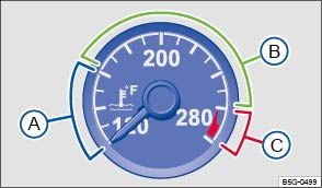 Fig. 200 Engine coolant temperature gauge in the instrument cluster: Ⓐ Engine cold; Ⓑ Normal temperature range; Ⓒ Warning zone.Read and follow the introductory information and safety information first⇒Introduction to the subject
If the indicator in the engine coolant temperature gauge is located in the cold range Ⓐ, the engine has not reached operating temperature. High engine speeds and heavy engine loads should be avoided.
Under normal driving conditions, the needle should be in the middle of the gauge. The temperature may go higher when the engine is working hard, especially in hot weather.
When the ignition is switched on, several warning and indicator lights come on briefly for a function check. They go out after a few seconds.
The following table explains what to do if the engine coolant temperature warning light does not go out a few seconds after the engine is started or starts flashing while driving.
| Flashes |
Temperature gauge needle ⇒ Fig. 200 |
Possible cause | Proper response |
|---|---|---|---|
|
|
Ⓒ Warning zone |
Engine coolant temperature too high. |
Pull off the road and stop as soon as you can do so safely. Stop the engine and let it cool down until the temperature needle is in the normal range again. Check the engine coolant level and add engine coolant if needed ⇒ Checking engine coolant level and topping off . If the engine coolant level is correct or the problem continues after adding coolant and driving a short distance, do not drive any farther. Contact the nearest authorized Volkswagen dealer or authorized Volkswagen Service Facility. If the coolant level is correct, the overheating may be caused by a radiator fan fault. Check the fuses and replace as necessary ⇒ Fuses . |
|
Ⓑ Normal range |
Engine coolant level too low. |
Check the engine coolant level after the engine has cooled down and add engine coolant if low ⇒ Engine coolant . If the engine coolant level is correct or the problem continues after adding coolant, do not drive any farther. Contact an authorized Volkswagen dealer or authorized Volkswagen Service Facility. These instructions apply only when the coolant temperature stays in the normal range. Stop immediately if the needle goes into the red warning zone ⇒ Fig. 200Ⓒ . |
|
| – | Engine coolant system malfunction. |
Pull off the road and stop as soon as you can do so safely. Get assistance from an authorized Volkswagen dealer, an authorized Volkswagen Service Facility, or another qualified workshop. |
|
| – |
Ⓐ Cold range |
The engine has not yet warmed up. | Do not drive at high engine speeds or with heavy engine loads until the engine warms up. |
When the ignition is switched on, several warning and indicator lights come on briefly for a function check. They go out after a few seconds.
WarningFailure to heed warning lights and instrument cluster text messages can cause the vehicle to break down in traffic and result in a collision and serious personal injury.
NoteFailure to heed warning lights or text WARNINGS can result in vehicle damage.
Displayed in color on an instrument cluster with color display.
Read and follow the introductory information and safety information first⇒Introduction to the subject
The engine cooling system is filled at the factory with a mixture of specially conditioned water and at least 40 percent of Volkswagen engine coolant additive G 13 (TL-VW 774 J). This engine coolant additive is pink.
This mixture provides antifreeze protection down to -13 °F (-25 °C). It also helps to protect the light alloy parts in the engine cooling system against corrosion. In addition, the mixture helps prevent calcium deposits and increases the boiling point of the engine coolant.
To protect the engine, the mixture must always contain at least 40% coolant additive even in warm weather or climates where antifreeze protection is not needed.
If more antifreeze protection is needed for climate conditions, the percentage of coolant additive can be increased. However, the coolant additive percentage must never be more than 60%; otherwise, antifreeze protection is reduced and the ability of the mixture to cool the engine is also reduced.
When adding engine coolant, use a mixture of distilled water and at least 40% coolant additive - G 13 - or - G 12 plus-plus - (TL-VW 774 G) for optimum corrosion protection ⇒ .
Do not mix - G 13 - with - G 12 plus - or - G 11 -. Mixing these coolant additives together significantly reduces corrosion protection ⇒ and can lead to engine damage that is not covered by any Volkswagen Limited Warranty.
WarningToo little antifreeze protection in the engine cooling system can cause engine failure and severe injuries.
NoteNever mix original Volkswagen engine coolant additives with other additives not approved by Volkswagen. Mixing Volkswagen coolant additives with coolant additives made by other manufacturers can seriously damage the engine and the engine cooling system.
Engine coolant and engine coolant additives can pollute the environment. Collect leaking operating fluids and dispose of them properly in accordance with applicable environmental laws and regulations.
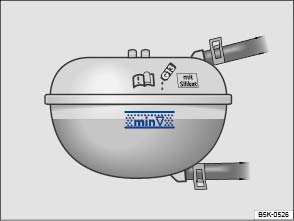 Fig. 201 Coolant expansion tank in the engine compartment.
 Fig. 202 Coolant expansion tank cap in the engine compartment.Read and follow the introductory information and safety information first⇒Introduction to the subject
If the coolant level drops too low, the engine coolant level/temperature warning light comes on.
. . . . As soon as possible, have the correct coolant ratio restored using engine coolant that meets Volkswagen specifications ⇒ Engine coolant specifications .WarningHot steam and hot engine coolant can cause serious burns.
Note
Introduction to the subjectIn this chapter you will find information on the following subjects:⇒ Warning light ⇒ Checking the vehicle battery electrolyte level ⇒ Charging, replacing, disconnecting, and connecting the vehicle battery
The standard 12 Volt vehicle battery is part of the vehicle electrical system.
Never do any work on the vehicle electrical system unless you
!If you are uncertain in any way, have the work done by an authorized Volkswagen dealer or authorized Volkswagen Service Facility. Serious personal injury may result from improperly performed work.
The 12 Volt vehicle battery is located in the engine compartment.
| Symbol | Meaning |
|---|---|
|
|
Always wear eye protection! |
|
|
Battery acid is highly corrosive. Always wear protective gloves and eye protection! |
|
|
Fire, sparks, open flame, and smoking are prohibited! |
|
|
When a battery is charged, it produces hydrogen gas which is highly explosive! |
|
|
Always keep children away from battery acid and vehicle batteries! |
WarningWorking on the batteries or the electrical system in your vehicle can cause serious acid burns, fires, explosions, or electrical shocks. Always read and heed the following WARNINGS and safety precautions before working on the batteries or the electrical system.
WarningCalifornia Proposition 65 Warning
Note
Emergency starting and starting the engine with a very weak vehicle battery or after the vehicle battery has been replaced may change or delete system settings (including time, date, personal convenience settings, and programming). Check the settings and correct as necessary once the vehicle battery has built up a sufficient charge.
Read and follow the introductory information and safety information first⇒Introduction to the subject
| Lights up | Proper response |
|---|---|
|
|
Alternator malfunction. See an authorized Volkswagen dealer or an authorized Volkswagen Service Facility. Have the electrical system checked. Switch off unnecessary electrical loads. The vehicle battery will not be charged by the alternator as you drive. |
When the ignition is switched on, several warning and indicator lights come on briefly for a function check. They go out after a few seconds.
WarningFailure to heed warning lights and instrument cluster text messages can cause the vehicle to break down in traffic and result in a collision and serious personal injury.
NoteFailure to heed warning lights or text WARNINGS can result in vehicle damage.
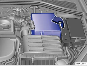 Fig. 203 In the engine compartment: Open the sleeve covering of the vehicle battery.Read and follow the introductory information and safety information first⇒Introduction to the subject
Check the electrolyte level of the battery regularly if the vehicle has high mileage (km), in places with a warm climate, and if the vehicle has an old battery. Otherwise the vehicle battery does not require maintenance.
.To open, fold the cover to the side in the direction of the arrow ⇒ Fig. 203 .
To close, fold the cover against the direction of the arrow.
| Color | Action |
|---|---|
| Light yellow or colorless | Battery electrolyte level is too low. The vehicle battery may need to be replaced. Have it checked by an authorized Volkswagen dealer or an authorized Volkswagen Service Facility. |
| Black | Battery electrolyte level is satisfactory. |
WarningWorking on the batteries can cause serious acid burns, explosion, or electrical shock.
Read and follow the introductory information and safety information first⇒Introduction to the subject
Vehicle batteries should be charged by an authorized Volkswagen dealer or an authorized Volkswagen Service Facility because the factory-installed battery requires a charger with overload protection ⇒ .
The battery in your vehicle is specially developed for its location, with special dimensions and safety features. Before buying a new battery, ask an authorized Volkswagen dealer or authorized Volkswagen Service Facility what batteries are suitable with regard to electro-magnetic compatibility, dimensions, required maintenance, performance, and safety specifications. Have the battery replaced by an authorized Volkswagen dealer or an authorized Volkswagen Service Facility.
Only use maintenance-free vehicle batteries meeting standards TL 825 06 and VW 7 50 73. These standards must date from July 2012 or later.
If the battery must be disconnected from the vehicle's electrical system, note the following:
. .After the battery is connected and the ignition is switched on, different indicator lights may light up. They should go out after you drive a short distance at 10–12 mph (15–20 km/h). If the indicator lights do not go out, contact an authorized Volkswagen dealer or an authorized Volkswagen Service Facility and have the vehicle checked.
If the battery was disconnected for a long time, the next scheduled service may not be correctly calculated and displayed ⇒ Instrument cluster . The maximum permissible service and maintenance intervals are shown in the ⇒BookletWarranty and Maintenance,.
If the ignition will not start after reconnecting the vehicle battery, lock the vehicle from the outside and unlock it again ⇒ Unlocking or locking the vehicle with Keyless Access . Then try to start the ignition again. If the ignition cannot be switched on, contact an authorized Volkswagen dealer, an authorized Volkswagen Service Facility, or another qualified workshop for assistance.
If the vehicle battery drain is high, the intelligent onboard electrical system management automatically takes steps to help prevent battery drain.
The onboard electrical system management cannot always keep the battery from being drained. For example, the battery will drain if the engine is not running, but the ignition is switched on or the parking lights are left on for a long time when parked.
WarningFailure to use the proper battery with proper mounting and connections may cause short circuits, fires, and serious personal injuries.
WarningWhen the vehicle battery is charged, it produces highly explosive hydrogen gas.
Note
Dispose of the vehicle battery according to regulations. Vehicle batteries contain poisonous substances such as sulfuric acid and lead.Battery acid can pollute the environment. Catch leaking operating fluids and dispose of them properly.
Introduction to the subjectIn this chapter you will find information on the following subjects:⇒ Washing the vehicle ⇒ Washing with a power washer ⇒ Cleaning windows and outside mirrors ⇒ Cleaning and changing the windshield wiper blades ⇒ Waxing and polishing vehicle paint ⇒ Caring for and cleaning chrome and aluminum parts ⇒ Cleaning wheel rims ⇒ Caring for rubber door and window seals ⇒ Deicing door lock cylinders ⇒ Undercoating ⇒ Cleaning the engine compartment
Regular and expert care helps to preserve the value of your vehicle. Such expert care may also be one of the requirements of your New Vehicle Limited Warranty if corrosion repair or repainting is necessary.
Vehicle care products are available from your authorized Volkswagen dealer or authorized Volkswagen Service Facility.
WarningVehicle care products can be dangerous. Improper use can cause accidents, burns, poisoning, or other serious personal injuries.
WarningImproper care and cleaning of vehicle components can impact the safety features of the vehicle and cause severe injuries.
NoteVehicle care products containing solvents can damage plastics and other vehicle the materials.Wash the vehicle only at specifically designated wash locations to help prevent water contaminated with oil, grease and fuel from entering the storm drain sewer system. In some areas it is against the law to wash motor vehicles anywhere than other than at specified designated car washing locations.When buying vehicle care products, try to choose those that are not harmful to the environment.Never throw out vehicle care products with ordinary household waste. Always read and heed all the instructions and all WARNINGS on the package.
Read and follow the introductory information and safety information first⇒Introduction to the subject
The longer insect splatter, bird droppings, tree sap, road dirt, industrial deposits, tar, soot, road salt, and other aggressive materials stay on your vehicle, the more damage they do to the paint finish. High temperatures (including strong sunlight) increase the corrosive effects. The vehicle underbody should also be washed regularly and thoroughly.
Pay close attention to the information provided by the car wash operator. Before going through a car wash, be sure to take the usual precautions to help prevent damage, such as closing the windows, folding back the outside mirrors, etc. If you have installed additional accessories on the vehicle, such as a spoiler, a roof rack, or an antenna, always ask the car wash operator if this poses a problem ⇒ .
The paint finish is tough enough that the vehicle can normally be washed without problems in an automatic car wash. However, the effect on the paint depends to a large extent on the type of car wash. Volkswagen recommends using brushless car wash facilities.
To remove wax residue from the windows and avoid jerky windshield wiper movement, heed the following tips ⇒ Cleaning windows and outside mirrors .
When washing by hand, first soften the dirt with plenty of water and then rinse off as much dirt as possible.
Then clean the vehicle with a soft sponge, a washing mitt or brush using only light pressure. Start on the roof and work down. Use special shampoo only on hard-to-remove dirt or grime.
Rinse the sponge or glove thoroughly and often.
Clean the wheels and under the door sills last. Use a different sponge or wash mitt.
WarningAfter the vehicle has been washed, the wet brakes or, in winter, brake discs or pads coated with ice, react slower and need longer stopping distances.
CautionSharp edges under the vehicle can cut exposed skin.
Note
NoteTo help prevent vehicle damage in a car wash:
Read and follow the introductory information and safety information first⇒Introduction to the subject
Always follow the instructions for the power washer. This especially applies to the pressure and spraying distance⇒ .
Make sure there is enough distance to soft materials such as rubber hoses or insulating material as well as any sensors that can be located on the front and rear of the vehicle, for example, the Park Distance Control system sensors (if equipped) ⇒ .
Never use concentrated jet nozzles or so-called dirt blasters⇒ .
Never use a power washer to clean the engine compartment ⇒ Cleaning the engine compartment .
WarningImproper use of power washers can cause serious invisible permanent damage leading to tire failure and loss of vehicle control. This can cause accidents and severe personal injury.
WarningAfter the vehicle has been washed, the wet brakes or, in winter, brake discs or pads coated with ice, react slower and need longer stopping distances.
Note
Read and follow the introductory information and safety information first⇒Introduction to the subject
Spray windows and outside mirrors with a commercially available alcohol-based window cleaner.
Dry windows and mirrors with a clean chamois or a lint-free cloth. Do not use a chamois that has been used to wipe painted surfaces because it will have absorbed an oily residue that will smear the glass surfaces.
Use window cleaner or a silicone remover to remove rubber, oil, grease and silicone deposits ⇒ .
Automatic car washes and vehicle care products can leave a wax residue on all glass surfaces. These wax residues can only be removed with special cleaners or cleaning cloths. Wax residue left on the windshield can cause the windshield wipers to grab and squeak instead of gliding smoothly. We recommend that after every car wash you remove any wax residue left on the windshield with a window cleaning cloth/chamois - G 052 522 A1 - or equivalent.
Windshield wiper squeak and grab can be reduced by filling the windshield washer fluid tank with a wiper fluid containing wax-removing agents. Make sure to maintain the proper mixing ratio when refilling the washer fluid tank. Grease-removing cleaning agents cannot remove wax residue ⇒ .
Windshield cleaners, special cleaners, and cleaning cloths are available from your authorized Volkswagen dealer and authorized Volkswagen Service Facility.
Remove snow from all windows and outside mirrors with an appropriate brush.
The best way to remove ice is with a deicer spray. When using an ice scraper always scrape in one direction, never back and forth. Dirt can scratch the glass when moving the scraper backward.
WarningDirty or fogged up windows reduce visibility and increase the risk of accidents and severe injuries.
Note
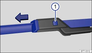 Fig. 204 Changing the windshield wiper blades.
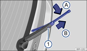 Fig. 205 Changing the rear window wiper blades.Read and follow the introductory information and safety information first⇒Introduction to the subject
Factory-installed wiper blades have a graphite coating. The graphite coating lets the wiper blades glide smoothly over the windshield. If this coating is worn or damaged, the wipers may grab or squeak.
Check all wiper blades regularly. Wiper blades that grab and squeak must be replaced if worn or damaged and cleaned if dirty ⇒ .
Replace worn or damaged wiper blades immediately. Replacement blades may be purchased from any authorized Volkswagen dealer or authorized Volkswagen Service Facility.
Move the front wiper arms to the service position before lifting them away from the windshield ⇒ Windshield wipers and washer .
It is not possible to lift the front wiper arms away from the windshield when they are not in the service position.
When lifting or replacing a wiper blade on a window, grip it only by its mounting and not by the blade itself.
.WarningWorn or dirty wiper blades reduce visibility and increase the risk of accidents and severe injuries.
Note
Read and follow the introductory information and safety information first⇒Introduction to the subject
A good coat of wax helps to protect the vehicle paint. When water no longer forms small drops and runs off when the paint is clean, apply a new coat of good hard wax to protect the vehicle again.
Even if a wax solution is used regularly at the car wash, Volkswagen recommends applying a coat of hard wax at least twice a year to protect the paint.
Polish your vehicle if the paint has lost its shine and the gloss cannot be brought back with wax.
The vehicle must be waxed after polishing if the polish used does not contain wax compounds to seal the paint.
Note
Read and follow the introductory information and safety information first⇒Introduction to the subject
NoteTo help prevent damage to chrome and aluminum parts:
NoteChrome wheel covers and hubcaps can have an extra coating. Do not treat them with chrome care or polishing products. Use regular paint care and polishing products.
Read and follow the introductory information and safety information first⇒Introduction to the subject
Stubborn brake dust can be removed with an industrial cleaner. Clean steel wheels regularly with a separate sponge.
Repair any paint damage on steel wheels before rust begins to form.
Every 2 weeks: Wash road salt and brake dust off alloy wheels, and clean the wheels with an acid-free detergent. Every 3 months: Volkswagen recommends applying a hard wax compound to the wheels.
If road salt and brake dust are not removed regularly, they can corrode the metal.
Use an acid-free detergent specifically designed for light alloy wheels. Do not use car polish or other abrasive products.
If the protective coating is damaged, for example by stone impact, repair the damaged area right away.
Read and follow the introductory information and safety information first⇒Introduction to the subject
The rubber seals around the doors and windows will stay soft and flexible, seal better and last longer if the seals are treated regularly with a suitable rubber care product.
Before applying the treatment, use a soft cloth to remove dust and dirt from the rubber seals.
Do not apply any rubber care products to the rubber seals on the body in the areas around the windows in the driver and front passenger doors. The product could run down onto the windows and smudge them.
Read and follow the introductory information and safety information first⇒Introduction to the subject
Volkswagen recommends using only genuine Volkswagen deicer spray with lubricating and anti-corrosive properties to deice door lock cylinders.
NoteLock deicers that contain grease solvents can cause the lock cylinder to rust.
Read and follow the introductory information and safety information first⇒Introduction to the subject
The vehicle underbody is coated to help protect it from corrosion and damage. The undercoating could be damaged during normal use. We therefore recommend that you have the protective coatings on the underbody and suspension inspected regularly, and repaired if necessary.
WarningUndercoating and rustproofing products can catch fire on the hot exhaust system or any other hot engine component.
Read and follow the introductory information and safety information first⇒Introduction to the subject
The engine compartment of a vehicle is a dangerous area ⇒ Working in the engine compartment .
If necessary, the engine compartment should be cleaned by an authorized Volkswagen dealer or authorized Volkswagen Service Facility. Incorrect cleaning procedures could remove corrosion protection and damage electrical components, among other things. In addition, water could enter directly into the vehicle interior through the plenum chamber ⇒ .
Never use a power washer to clean the engine compartment ⇒ .
If the engine compartment is extremely dirty, have it cleaned professionally by your authorized Volkswagen dealer or authorized Volkswagen Service Facility.
The plenum chamber is located in the engine compartment between windshield and engine, under a perforated cover. Outside air is taken into the vehicle interior from the plenum chamber via the climate control system.
Regularly remove leaves and other loose objects from the plenum chamber cover by hand or with a vacuum cleaner.
Have the area under the perforated cover cleaned by an authorized Volkswagen dealer or authorized Volkswagen Service Facility.
WarningInjuries, scalding, electric shock, accidents, and fire hazards can occur while working on the engine or in the engine compartment!
NoteSpraying or pouring water (for example, with a power washer) into the plenum chamber can cause severe damage to the vehicle.Wash the engine compartment only in special wash bays so that the oily dirt and fuel residue that are washed off the vehicle will not enter the sewage system. In some areas it illegal to wash the engine compartment anywhere other than at such specified locations.
Introduction to the subjectIn this chapter you will find information on the following subjects:⇒ Caring for upholstery ⇒ Cleaning upholstery, fabric trim, and microfiber fabric ⇒ Care and cleaning of leather upholstery ⇒ Cleaning leatherette ⇒ Cleaning storage compartments and cup holders ⇒ Care and cleaning of plastic components, wood trim, and instrument panel ⇒ Cleaning the safety belts
Modern clothing fabrics such as dark denim may not be completely colorfast. Even with normal use, dye from these and other fabrics can rub off on seat upholstery and leave visible discolorations (especially on light-colored seat upholstery). This is caused by a lack of colorfastness in the clothing fabric, not by any fault in the seat upholstery fabric. To help prevent damage to the seat upholstery, always make sure your clothing is colorfast. Volkswagen recommends having a qualified specialist remove any discolorations from the seat upholstery.
The longer stains, dirt and other deposits remain on the surfaces of vehicle components and upholstery, the more difficult it may be to clean them. If stains, dirt and deposits are left untreated for a long time, they may become impossible to remove.
WarningVehicle care products can be dangerous. Improper use can cause accidents, burns, poisoning, or other serious personal injuries.
WarningImproper care and cleaning of vehicle components can compromise the vehicle's safety features and cause serious personal injury.
Note
Suitable care products are available from authorized Volkswagen dealers and authorized Volkswagen Service Facilities.
Read and follow the introductory information and safety information first⇒Introduction to the subject
Open Velcro® fasteners can damage upholstery, fabric, and trim. Before you get into the vehicle, close all Velcro® fasteners that could come into contact with upholstery fabrics and cloth trim.
Sharp-edged objects and items on clothing and belts (such as belt clips, mobile phone cases, zippers, rivets, and rhinestones) can damage upholstery material and fabric trim. To help prevent damage, do not let such items come into direct contact with the upholstery and fabric trim.
Dust and dirt particles in pores, folds, and seams can have a scouring effect on material and damage the surface. Remove dust and dirt regularly to help prevent permanent surface damage.
Check clothing for color-fastness to help prevent upholstery discoloration, especially to light-colored upholstery.
NoteDisregarding the upholstery-related checklist may lead to damage or discoloration of upholstery and fabric trim.
Volkswagen recommends having any discoloration removed by an authorized Volkswagen dealer or authorized Volkswagen Service Facility.
Read and follow the introductory information and safety information first⇒Introduction to the subject
Airbag components and electrical connectors may be installed in the driver seat, the front passenger seat, and in the outer rear seats. Damaging, cleaning and handling incorrectly, or wetting or soaking these seat surfaces and backrests can damage the vehicle electrical system and prevent the airbag system from working properly ⇒ .
Electrical components and connectors that could be damaged by incorrect cleaning or handling are installed in power seats and heated seats ⇒ . This can also result in damage to other parts of the vehicle electrical system.
For this reason, read and follow these cleaning instructions:
. .Upholstery and fabric trim with light generalized soiling can be cleaned with a commercially available dry-foam cleaner.
If the upholstery and fabric trim pieces are heavily soiled, see your authorized Volkswagen dealer or authorized Volkswagen Service Facility before you begin cleaning to learn about suitable cleaning options. If necessary, have the cleaning done by a professional.
When treating stains, it may be necessary to clean the entire surface and not just the stain itself. This is especially true if the entire surface has become dirty from normal use. Otherwise, the area that is treated may become lighter than the untreated area. If you have questions or concerns, consult a professional cleaner.
| Type of stain | Recommended cleaning for fabric and upholstery |
|---|---|
| Water-based stains, such as coffee or fruit juice. |
– Moisten a sponge with water and rub the stain gently with a circular motion. – Wipe dry with an absorbent cloth. |
| Persistent stains, such as chocolate or make-up. |
– Use only Volkswagen-approved cleaning products. – If necessary, have the fabric or upholstery professionally cleaned. |
| Grease-based stains, such as oil, lipstick, etc. |
– Use only Volkswagen-approved cleaning products. – If necessary, have the fabric or upholstery professionally cleaned. |
WarningIf there is a malfunction in the airbag system, the airbag may not deploy correctly or at all, or it may deploy unexpectedly. This could cause fatal injuries.
NoteIf the upholstery on power seats, heated seats, or seats with airbag components is wet, electrical components and the vehicle electrical system could be damaged.
Note
Note
Read and follow the introductory information and safety information first⇒Introduction to the subject
If you have questions regarding the care and cleaning of the leather upholstery in the vehicle, please contact an authorized Volkswagen dealer or authorized Volkswagen Service Facility.
Natural leather requires special attention and care. Napa leather has a smooth surface. The intensity of the color application determines the leather's appearance and texture. If you can see the leather grain and other natural characteristics, this is an untreated napa leather that will provide very comfortable seating. Delicate veins, closed scars, insect bites, folds, and a slightly clouded color remain visible and represent authentic characteristics of the natural material. Untreated napa leather has no protective coating. It is therefore more susceptible to damage. You should keep this in mind if the leather is going to be exposed to severe wear from children, animals, or other factors. By contrast, leather that has a protective coating is more robust. This has a positive effect on the leather's durability in daily use. The typical natural characteristics are hardly visible or no longer visible at all, but that has no impact on the quality of the leather itself. The typical characteristics of untreated leather are much more distinctive than those of a surface-treated leather.
.Volkswagen recommends using a slightly moistened cotton or wool cloth for general cleaning.
It is important not to let water soak through the leather or penetrate into seams.
Before cleaning leather surfaces, read and heed the information ⇒ Cleaning upholstery, fabric trim, and microfiber fabric .
| Type of stain | Cleaning |
|---|---|
| Heavy stains |
– Apply a mild soapy solution with a cloth that has been wrung nearly dry. – Dab dry with an absorbent cloth. |
| Water-based stains, such as coffee, tea, juice, or blood. |
– Remove fresh stains with an absorbent cloth. – If the stains are already dry, use an appropriate cleaning agent ⇒ .
|
| Grease-based stains, such as oil, lipstick, etc. |
– Remove fresh stains with an absorbent cloth. – Use an appropriate cleaning agent on stains that have not yet penetrated the surface ⇒ .
|
| Special stains, such as ballpoint pen, marker, nail polish, latex paint, or shoe polish. |
– Dab dry with an absorbent cloth. – Clean with a special stain remover designed for leather. |
Note
Slight discoloration caused by wear and tear is normal.
Mild soap solution: 2 tablespoons of liquid soap in 1 quart (liter) of water.
Read and follow the introductory information and safety information first⇒Introduction to the subject
Clean leatherette upholstery only with water and a mild soap solution.
Before cleaning leatherette surfaces, read and heed the information ⇒ Cleaning upholstery, fabric trim, and microfiber fabric .
Note
Read and follow the introductory information and safety information first⇒Introduction to the subject
Some storage compartments and cup holders may have a removable rubber or felt insert at the bottom.
Read and follow the introductory information and safety information first⇒Introduction to the subject
.WarningUsing solvents or other improper cleaning products on surfaces where airbags are located can change the way airbags deploy in a crash.
Read and follow the introductory information and safety information first⇒Introduction to the subject
If a safety belt is dirty, this can prevent the belt from working properly. Keep safety belts clean and regularly check all safety belts for damage.
Safety belts must never be taken apart for cleaning.
.WarningDamage to safety belts reduces their overall effectiveness and increases the risk of serious personal injury and death whenever the vehicle is being used.
Introduction to the subjectIn this chapter you will find information on the following subjects:⇒ Break-in period ⇒ Parts and accessories ⇒ Operating fluids and equipment ⇒ Repairs and technical modifications ⇒ Repairs and other things that can affect Advanced Airbag performance ⇒ Notice about data recorded by the Event Data Recorder and vehicle control modules ⇒ Using a mobile phone in a motor vehicle when it is not connected to a vehicle telephone antenna: Some important things to know WarningInappropriate spare parts and accessories as well as improperly performed work, modifications and repairs can cause vehicle damage, accidents and serious personal injuries.
Read and follow the introductory information and safety information first⇒Introduction to the subject
Note applicable requirements for breaking in new parts.
A new engine must be carefully broken in during the first 1000 miles (1600 kilometers). During the first few hours of driving, the engine's internal friction is higher than later when all moving parts have been broken in.
Engine life is influenced by how you drive the vehicle for the first 1000 miles (1600 km). Even afterwards, driving at moderate engine speeds, especially when the engine is cold, will tend to reduce engine wear and help the engine to last longer and go farther. But do not drive at an excessively low engine speed, either. Always downshift if the engine is not running smoothly. For the first 600 miles (1000 km):
From 600 to 1000 miles (1000 to 1600 km): Speed may gradually be increased to maximum permissible road and engine speed.
Breaking in a new engine gently will increase service life and reduce oil consumption.
Read and follow the introductory information and safety information first⇒Introduction to the subject
Volkswagen recommends that you consult an authorized Volkswagen dealer or authorized Volkswagen Service Facility before purchasing accessories, spare parts or other equipment. Always do so if you want to install additional accessories or replace parts. Your authorized Volkswagen dealer or authorized Volkswagen Service Facility can provide information about legal requirements and factory-recommended accessories, spare parts, and other equipment.
WarningImproper vehicle modifications and repairs affect the performance of the airbag system and cause malfunctions and severe personal injuries.
Read and follow the introductory information and safety information first⇒Introduction to the subject
Operating fluids and parts that wear out with use (such as timing belts, tires, engine coolants, engine oils, spark plugs, and vehicle batteries) are constantly being improved. For this reason, it is important to have operating fluids changed and wearing parts replaced by an authorized Volkswagen dealer or authorized Volkswagen Service Facility. Authorized Volkswagen dealers and authorized Volkswagen Service Facilities are always up-to-date regarding new developments and changes.
WarningImproper use of operating fluids and equipment can cause accidents, serious personal injuries, burns and/or poisoning.
Note
Leaking operating fluids can pollute the environment. Collect leaking operating fluids in suitable containers and dispose of them properly in accordance with applicable environmental laws and regulations.
Read and follow the introductory information and safety information first⇒Introduction to the subject
Volkswagen guidelines for repairs and technical modifications must be followed⇒ !
Changes to electronic components and related software can cause malfunctions. These malfunctions can also affect other systems that are related to the component or software that was modified. The vehicle's operational safety can be seriously jeopardized, increased vehicle component wear can occur, and the vehicle may no longer meet applicable emissions requirements.
Volkswagen recommends having all repairs and technical modifications performed by an authorized Volkswagen dealer or authorized Volkswagen Service Facility using Genuine Volkswagen Parts.
Damage that is caused by improper repairs or unapproved technical modifications will not be covered by any Volkswagen Limited Warranty.
WarningImproperly performed repairs and modifications can cause vehicle damage and malfunctions, and can impair the efficiency of driver assistance systems. This can lead to accidents and severe personal injuries.
NoteImproperly performed repairs and modifications can cause increased component wear and result in vehicle emissions that no longer meet applicable requirements.
Read and follow the introductory information and safety information first⇒Introduction to the subject
Repairs and modifications of front bumpers, doors, front seats, headliners and the chassis can affect proper airbag performance and should be performed by an authorized Volkswagen dealer or authorized Volkswagen Service Facility. These vehicle areas can contain important parts of the airbag system.
Components of the airbag system can be damaged during removal, assembly and repair activities on the airbag system itself or related components. Damage to airbag parts can prevent the system from working properly in a collision.
Observe all regulations so that the effectiveness of the airbag is not affected and to prevent disassembled parts from causing injuries and pollution. Authorized Volkswagen dealers, authorized Volkswagen Service Facilities, and other qualified workshops are familiar with these regulations.
Changing the vehicle's suspension system can change the way that the airbag system works in a crash. For example, using tire-rim combinations not approved by Volkswagen, lowering the vehicle, changing the stiffness of the suspension, including the springs, suspension struts, shock absorbers etc. can change the forces that are measured by the airbag sensors and sent to the electronic control unit. Some suspension changes can, for example, increase the force levels measured by the airbag sensors and sent to the electronic control unit and make the airbag system deploy in crashes in which it would not deploy if the changes had not been made. Other kinds of changes may reduce the force levels measured by the sensors and prevent the airbag from deploying when it should.
Never install leather upholstery on a vehicle that originally had cloth upholstery. Never install cloth upholstery on a vehicle that originally had leather upholstery. The capacitive passenger detection system for the Advanced Airbag system will not work properly if different upholstery is installed on the passenger seat than the upholstery originally installed on the vehicle when it was originally manufactured.
WarningChanging the vehicle's suspension including use of unapproved tire-rim combinations can change airbag performance and increase the risk of serious personal injury in a crash.
WarningLeaving the optional safety belt extender attached to the safety belt buckle on the front passenger seat when the safety belt is not being used will prevent the Advanced Airbag System from working properly and can increase the risk of serious personal injury in a collision.
WarningItems stored between the safety belt buckle and the center console can cause safety belt buckle to send the wrong information to the airbag control unit and prevent the Advanced Airbag System from working properly.
WarningImproper care and servicing, and improper modification and repair work, can increase the risk of personal injury and death by preventing an airbag from deploying when needed or deploying an airbag unexpectedly:
Undeployed airbag modules and safety belt pretensioners are classified as Perchlorate Material. Special handling may apply – see http://www.dtsc.ca.gov/hazardouswaste/perchlorate. Obey all applicable legal requirements regarding handling and disposal of the vehicle or parts of its restraint system, including airbag modules and safety belts with pretensioners. Authorized Volkswagen dealers and authorized Volkswagen Service Facilities are familiar with the requirements, and we recommend that you have them perform this service for you.
Read and follow the introductory information and safety information first⇒Introduction to the subject
This vehicle is equipped with an Event Data Recorder (EDR). The main purpose of an EDR is to record, in certain crash or near crash-like situations, such as an airbag deployment or hitting a road obstacle, data that will assist in understanding how a vehicle's systems performed. The EDR is designed to record data related to vehicle dynamics and safety systems for a short period of time, typically 30 seconds or less. The EDR in this vehicle is designed to record such data as:
These data can help provide a better understanding of the circumstances in which crashes and injuries occur. NOTE: EDR data are recorded by your vehicle only if a non-trivial crash situation occurs; no data are recorded by the EDR under normal driving conditions and no personal data (e.g., name, gender, age, and crash location) are recorded. However, other parties, such as law enforcement, could combine the EDR data with the type of personally identifying data routinely acquired during a crash investigation.
To read data recorded by an EDR, special equipment is required, and access to the vehicle or the EDR is needed. In addition to the vehicle manufacturer, other parties, such as law enforcement, that have the special equipment, can read the information if they have access to the vehicle or the EDR.
Some state laws restrict the retrieval or downloading of data stored by EDRs installed in a vehicle for the express purpose of retrieving data after an accident or crash event without the owner's consent.
Volkswagen will not access the EDR and/or similar data or give it to others - unless the vehicle owner (or lessee if the vehicle has been leased) agrees, or;
Volkswagen may also use the data for research about vehicle operation and safety performance or provide the data to a third party for research purposes without identifying the specific vehicle or information about the identity of its owner or lessee.
NOTE: Your vehicle may be equipped with Volkswagen Car-Net. Please see ⇒ Volkswagen Car-Net and the Volkswagen Car-Net Terms of Service and Privacy Policy at (http:// www.vw.com/carnet) for details regarding how Volkswagen collects, processes, transmits, uses and shares information obtained through the Volkswagen Car-Net equipment and service.
Your vehicle is also equipped with a number of electronic control modules for various vehicle systems, such as engine management, emission control, airbags, and safety belts.
These electronic control modules record data during normal vehicle operation that may be needed by trained technicians for diagnostic and repair purposes. The recording capability of these modules is limited to data (no sound is recorded). Only a small amount of data is actually recorded over a very limited period of time, or stored when a system fault is detected by a control module. Some of the data stored may relate to vehicle speed, direction, or braking, as well as restraint system use and performance in the event of a crash. Stored data can also only be read and downloaded with special equipment that is directly connected to the vehicle.
Read and follow the introductory information and safety information first⇒Introduction to the subject
Mobile or cellular telephones send and receive radio waves, sometimes called radiofrequency energy (RF energy), both when they are being used and when they are in standby mode. Current scientific literature indicates that radio waves that exceed a certain level can have effects on the human body. Limits and guidelines have been established by governmental authorities and international committees in an effort to keep the electromagnetic radiation from mobile phones at levels that will not cause health problems. However, there is no scientifically based proof that wireless phones are absolutely safe.
Therefore, some experts recommend a precautionary approach regarding the use of mobile phones by taking measures that lower the personal exposure to electromagnetic fields. When using a mobile telephone inside a motor vehicle without a proper connection to an integrated vehicle telephone antenna, the personal exposure to electromagnetic fields will be higher than when using the mobile telephone while properly connected to an integrated or other outside vehicle telephone antenna.
Your vehicle may be equipped with an optional hands-free system that will permit many of the features of compatible Bluetooth enabled mobile telephones to be used for greater convenience and is consistent with the laws of an increasing number of states and localities that prohibit the use of mobile telephones without some kind of hands-free device.
The hands-free system in your vehicle can be used with certain mobile phones that are connected by wire and hardware connector or via compatible Bluetooth enabled phones with a cradle that is designed to fit your mobile telephone. The special cradle offers several advantages: The phone cradle must be safely secured to the base plate. Your phone is firmly attached to the instrument panel and is within reach at all times. Placing the phone in its cradle permits it to be charged, but more importantly connects the mobile phone to the vehicle's outside antenna. A mobile telephone that is properly connected to the integrated or other outside vehicle telephone antenna will lower the personal exposure to electromagnetic fields. You should also experience a better quality of service. Although a mobile telephone can be used inside your vehicle without a cradle, the phone will not be securely attached to the vehicle, will not be charged through the cradle wiring, and more importantly will not be connected to the vehicle's integrated telephone antenna. The mobile phone will also not be recharged. You might also experience more dropped calls and an overall impaired quality of the connection.
Therefore we strongly recommend that you use your mobile telephone in your vehicle only when it is properly attached to an appropriate cradle mounted on a base plate on the instrument panel.
Because of the large number and variety of mobile telephones on the market and the frequency with which new models are introduced, Volkswagen does not offer cradles for mobile telephones. Please check with the manufacturer of the mobile telephone that you plan to use.
Bluetooth is a registered trademark of Bluetooth SIG, Inc.
WarningA mobile phone on the seat, instrument panel or in other places can be thrown around the inside of the vehicle during a sudden braking maneuver, a crash or other accident and injure vehicle occupants.
WarningUsing a mobile phone or CB radio inside the vehicle without a properly installed and separate outside antenna can be dangerous to your health and that of your passengers because the electromagnetic radiation energy that mobile phones and CB radios emit may be above established limits. This also applies if the outside antenna is not installed properly.
Introduction to the subjectIn this chapter you will find information on the following subjects:⇒ Operating your vehicle outside of the United States and Canada ⇒ Radio antenna and reception ⇒ Component protection ⇒ Volkswagen service information WarningImproper vehicle care and use, as well as improper changes to the vehicle, increase the risk of accidents and injuries.
NoteImproper vehicle care and use, as well as improper changes to the vehicle, can result in damage to the vehicle.
Read and follow the introductory information and safety information first⇒Introduction to the subject
Government regulations in the United States and Canada require that automobiles meet specific emission regulations and safety standards. Therefore, vehicles built for the U.S. and Canada differ from vehicles sold in other countries.
If you want to drive the car in another country for a short time, please see the information in ⇒ Driving in other countries .
If you plan to take your vehicle outside the continental limits of the United States or Canada, there is the possibility that:
NoteVolkswagen is not responsible for mechanical damage that may result from substandard fuel or service or the unavailability of Genuine Volkswagen parts.
Read and follow the introductory information and safety information first⇒Introduction to the subject
If the Infotainment system was installed at the factory, the radio antenna may be installed in different locations in the vehicle:
Antennas on the insides of windows are thin wires.
NoteAntennas installed on the insides of windows can be damaged by abrasive objects or by corrosive or acidic cleaning agents or other chemicals. Do not place any stickers on the windshield-integrated antenna and never clean the antenna with corrosive or acidic cleaning agents or other chemicals.NoteIf retrofitting a radio or a navigation system, make sure that the vehicle's standard integrated antenna amplifier is compatible with the radio or navigation system. If not, use an additional antenna adapter. Otherwise, the antenna amplifier could be overloaded and damaged.Operating electrical devices near the integrated windshield antenna may interfere with AM radio reception.
Read and follow the introductory information and safety information first⇒Introduction to the subject
Some electronic components and control units in the vehicle may be equipped with a component protection feature, for example, the Infotainment system.
Component protection is a protective feature that helps to:
If a component protection-related message appears in the instrument cluster display or the infotainment system display, see an authorized Volkswagen dealer or an authorized Volkswagen Service Facility for assistance.
Read and follow the introductory information and safety information first⇒Introduction to the subject
Volkswagen service information is published as soon as possible after model introduction.
To order service information contact:
Volkswagen Technical Literature Ordering Center
www.vw.techliterature.com
WarningImproperly performed repairs and modifications can cause vehicle damage and malfunctions, and can impair the efficiency of driver assistance systems and the airbag system. This can lead to accidents and severe personal injuries.
Radio Frequency Devices and Radiocommunication Equipment User Manual Notice.
FCC Part 15.19
These devices comply with Part 15 of the FCC Rules. Operation is subject to the following 2 conditions:
(1) This device may not cause harmful interference, and
(2) this device must accept any interference received, including interference that may cause undesired operation.
FCC Part 15.21
CAUTION:
Changes or modifications not expressly approved by the party responsible for compliance could void the user's authority to operate the equipment.
These devices comply with RSS-210 of Industry Canada.
Operation is subject to the following 2 conditions:
(1) This device may not cause interference, and
(2) this device must accept any interference, including interference that may cause undesired operation of the device.
The manufacturer is not responsible for any radio or TV interference caused by unauthorized modifications to this equipment.
If you believe that your vehicle has a defect which could cause a crash or could cause injury or death, you should immediately inform the National Highway Traffic Safety Administration (NHTSA) in addition to notifying Volkswagen of America, Inc. 3800 Hamlin Road, Auburn Hills, MI 48326.
If NHTSA receives similar complaints, it may open an investigation, and if it finds that a safety defect exists in a group of vehicles, it may order a recall and remedy campaign. However, NHTSA cannot become involved in individual problems between you, your dealer, or Volkswagen of America, Inc.
To contact NHTSA, you may call the Vehicle Safety Hotline toll-free at 1-888-327-4236 (TTY: 1-800-424-9153);
go to http://www.nhtsa.gov;
or write to:
|
Administrator NHTSA 1200 New Jersey Avenue, SE. Washington, D.C. 20590 |
| You can also obtain other information about motor vehicle safety from http://www.safercar.gov. |
Introduction to the subjectIn this chapter you will find information on the following subjects:⇒ Indicator lights ⇒ Catalytic converter WarningThe vehicle exhaust system and the catalytic converter or diesel particulate filter get very hot. They can cause fires and serious personal injury.
WarningCalifornia Proposition 65 Warning
Read and follow the introductory information and safety information first⇒Introduction to the subject
| Lights up | Possible cause | Proper response |
|---|---|---|
|
|
Engine control malfunction (Electronic Power Control). | Have engine checked immediately by an authorized Volkswagen dealer or authorized Volkswagen Service Facility. |
|
|
Engine speed (rpm) limited (if equipped). |
On some vehicles, the engine speed (rpm) may be automatically limited to the engine speed shown in the instrument cluster display to help prevent the engine from overheating. Once the engine is no longer at a critical temperature and you have briefly taken your foot off the accelerator, the engine speed limit is increased. If the engine speed is limited due to a malfunction in the engine management system, the |
|
|
Engine control/monitoring system malfunction (engine Malfunction Indicator Light - MIL) | Ease off the accelerator. Carefully drive to the nearest authorized Volkswagen dealer or authorized Volkswagen Service Facility. Have engine checked. |
| Flashes | Possible cause | Proper response |
|---|---|---|
|
|
Misfire, which can damage the catalytic converter. | Ease off the accelerator. Carefully drive to the nearest authorized Volkswagen dealer or authorized Volkswagen Service Facility. Have engine checked. |
When the ignition is switched on, several warning and indicator lights come on briefly for a function check. They go out after a few seconds.
NoteFailure to heed warning lights or text WARNINGS can result in vehicle damage.As long as the indicator lights or
are on, expect engine malfunctions, increased fuel consumption, and loss of engine efficiency.
Displayed in color on an instrument cluster with color display.
Read and follow the introductory information and safety information first⇒Introduction to the subject
The catalytic converter provides exhaust gas after-treatment to help reduce pollutants in the exhaust gas. To help ensure long service life of the exhaust system and gasoline engine catalytic converter:
If you experience misfires, loss of power or the engine is not running smoothly while driving, reduce speed immediately and have the vehicle checked by an authorized Volkswagen dealer or authorized Volkswagen Service Facility. Otherwise, gasoline could reach the exhaust system and get into the atmosphere. The catalytic converter could also be damaged by overheating!
Under certain engine conditions, you may smell a sulfur odor. This is not an indication of a malfunctioning emission control system. This depends upon the sulfur content of the fuel.
1
(Power outlets)
3
3-button moduleInformation button
(3-button module)
(3-button module)
(3-button module)
(3-button module)
A
(Operating your vehicle outside of the United States and Canada)
Extended stays with the vehicle
(Operating your vehicle outside of the United States and Canada)
(Operating your vehicle outside of the United States and Canada)
(Braking assistance systems)
(Adaptive Cruise Control (ACC))
(Performance Monitor sport gauges)
(Parts, accessories, repairs, and modifications)
(Warning and indicator lights)
(Switching lights on and off)
Warning and indicator lightsAdaptive Cruise Control (ACC)Indicator lights
(Display, warning and indicator lights)
(Operating Adaptive Cruise Control (ACC))
Radar sensorSpecial driving situationsWarning lights
(Display, warning and indicator lights)
Adaptive Front Lighting System
(Lights and vision – features)
(Proper seating position)
Electrical controls on the front seats
(Electrical controls on the driver and front passenger seats)
(Adjusting the front and rear head restraints)
Manual controls on the front seats
(Manual controls on the driver and front passenger seats)
Proper seating positionRear seat backrest
(Folding the rear seat backrest forward and back into place)
(Adjusting the steering wheel position)
(Adjusting the Custom driving mode)
(Advanced Airbag System components)
(Lights and vision – features)
(Repairs and technical modifications)
(Heating and air conditioning)
Air recirculationAir ventsClimatronic
(Climatronic controls)
ControlsManual controlsClimatronic controlsOperation via the Infotainment system
(Manual controls)
(Operation via the Infotainment system)
(Operation)
(Manual controls)
(Operation)
(Operation)
Air recirculationFunctionality
(Air recirculation)
(Air recirculation)
(Description of the power locking system)
(Advanced Airbag System components)
(How to tell if the front passenger front airbag is on or off)
Capacitive passenger detection system
(How to tell if the front passenger front airbag is on or off)
(Care and cleaning of plastic components, wood trim, and instrument panel)
Deactivation of the front passenger front airbag
(How to tell if the front passenger front airbag is on or off)
(Airbags and how they work)
(Airbags and how they work)
(Monitoring the Advanced Airbag System)
Locking vehicle after inflation
(Description of the power locking system)
PASSENGER AIR BAG lightSide airbagsSide Curtain Protection airbags (2-door vehicles)
(Side Curtain Protection airbags for 2-door vehicles)
Side Curtain Protection airbags (4-door vehicles)
(Side Curtain Protection airbags for 4-door vehicles)
(How to tell if the front passenger front airbag is on or off)
(Care and cleaning of plastic components, wood trim, and instrument panel)
(Remote control vehicle keys)
(Anti-theft alarm system)
(Winter tires)
Snow chainsWinter tiresAluminum parts
(Caring for and cleaning chrome and aluminum parts)
(Interior and reading lights)
(Caring for and cleaning chrome and aluminum parts)
(Radio antenna and reception)
(Braking assistance systems)
(Braking assistance systems)
Anti-theft alarm systemAnti-theft wheel bolts
(Contents)
(Engine coolant specifications)
(Application software (“apps”))
(Center armrest (Golf, Golf GTI))
(Center armrest (Golf, Golf GTI))
(Center armrest (Golf R))
(Braking assistance systems)
See Braking assistance systemsBraking assistance systemsSwitching Anti-Slip Regulation (ASR) and ESC Sport mode on and off
(Braking assistance systems)
(Switching Anti-Slip Regulation (ASR) and ESC Sport mode on and off)
(Tire Pressure Monitoring System (TPMS) and recalibration through the Infotainment system)
Adaptive Cruise Control (ACC)Anti-Lock Brake System (ABS)
(Braking assistance systems)
Anti-Slip Regulation (ASR)Braking assistance systemsSwitching Anti-Slip Regulation (ASR) and ESC Sport mode on and off
(Braking assistance systems)
(Auto Hold (Golf R))
Automatic Post-Collision Braking System
(Braking assistance systems)
Blind Spot Monitor with Rear Traffic AlertBrake Assist (BAS)
(Braking assistance systems)
Braking assistance systemsCruise controlCruise controlDriving Mode SelectionDynamic Chassis Control (DCC)
(Driving Mode Selection)
Electronic Differential Lock (EDL and XDL)
(Braking assistance systems)
Electronic Stability Control (ESC)
(Braking assistance systems)
(Forward Collision Warning (Front Assist))
(Hill Start Assist (Hill Hold))
(Lane Keeping System (Lane Assist))
Park AssistPark Distance Control
(Park Distance Control (PDC))
Rear View Camera systemTire Pressure Monitoring System (TPMS)
(Tire Pressure Monitoring System (TPMS) and recalibration through the Infotainment system)
(Using jumper cables)
(Indicator light)
(Inside mirror)
(Lights and vision – features)
(Instrument panel lighting and headlight range adjustment)
(Charging, replacing, disconnecting, and connecting the vehicle battery)
Automatic Post-Collision Braking System
(Braking assistance systems)
(Automatic transmission: Selector lever)
(Vehicle key positions in the ignition switch)
(Driving with automatic transmission)
(Driving with automatic transmission)
(Driving with automatic transmission)
Emergency release for the selector lever lockKick-down feature
(Driving with automatic transmission)
(Driving with automatic transmission)
MalfunctionAutomatic transmission malfunctionShiftingShiftingAutomatic transmission: Selector lever
(Shifting)
TowingTowing on a commercial tow truckTips on towing
(Towing on a commercial tow truck)
(Vehicle key positions in the ignition switch)
(Forward Collision Warning (Front Assist))
(Storage compartment in the front center console)
(Weights and axle weights)
B
(Interior and reading lights)
(Braking assistance systems)
(Replacing the remote control vehicle key battery)
(Replacing the remote control vehicle key battery)
(Vehicle battery)
(Checking the vehicle battery electrolyte level)
Before taking the vehicle in to the shop
(Frequently asked questions (FAQ))
(Service and disposal of belt pretensioners)
(Service and disposal of belt pretensioners)
(Service and disposal of belt pretensioners)
(Warning light)
(Blind Spot Monitor with Rear Traffic Alert)
(Blind Spot Monitor)
Indicator lightsIndicator lights in the outside mirrors
(Blind Spot Monitor)
(Blind Spot Monitor with Rear Traffic Alert)
(Cup holders)
(Braking assistance systems)
(About the brakes)
(About the brakes)
(Braking and parking)
(About the brakes)
(Brake fluid)
(About the brakes)
Braking assistance systemsBreak-in period
(About the brakes)
(About the brakes)
(Brake fluid)
(Electronic parking brake (Golf R))
(Electronic parking brake (Golf R))
(Warning and indicator lights)
(Parking brake (Golf, Golf GTI))
(Warning and indicator lights)
Braking assistance systemsBreak-in period
(New and replacement tires)
(Break-in period)
The first few miles (kilometers)
(Break-in period)
(New and replacement tires)
(Protecting yourself and the vehicle)
C
California Proposition 65 Warning
(Vehicle battery)
(Rear View Camera system)
Capacitive passenger detection system
(How to tell if the front passenger front airbag is on or off)
(Outside mirrors)
(Outside mirrors)
(Auto Hold (Golf R))
(Features)
3-button moduleApplication software
(Application software (“apps”))
(Exterior care and cleaning)
(Indicator lights)
(Indicator lights)
(Indicator lights)
(Using a mobile phone in a motor vehicle when it is not connected to a vehicle telephone antenna: Some important things to know)
(Center armrest (Golf, Golf GTI))
(Center armrest (Golf, Golf GTI))
(Center armrest (Golf R))
(Upper center console)
Changing a wheelAfter the wheel change
(After changing a wheel)
(Lifting the vehicle with the vehicle jack (Golf))
Lifting the vehicle (Golf GTI, Golf R)
(Lifting the vehicle with the vehicle jack (Golf GTI, Golf R))
(Preparations for changing a wheel)
Removing the subwooferWheel boltsWhen more than one tire is damaged
(Changing a wheel)
(Replacing light bulbs)
(Checking the engine oil level and adding oil)
(Getting ready and driving safely)
(Checking the engine oil level and adding oil)
Before working in the engine compartment
(Preparing to work in the engine compartment)
(Protecting yourself and the vehicle)
(Checking the engine oil level and adding oil)
(Refueling checklist)
Driving in other countriesDriving safely
(Getting ready and driving safely)
(Getting ready and driving safely)
(Protecting yourself and the vehicle)
Lifting vehicle with jackLifting the vehicle with the vehicle jack (Golf)Lifting the vehicle with the vehicle jack (Golf GTI, Golf R)
(Lifting the vehicle with the vehicle jack (Golf))
Preparations for changing a wheelSafety belts
(Using safety belts)
(Preparations)
(Caring for upholstery)
(Refueling checklist)
(How to tell if the front passenger front airbag is on or off)
(Child restraints and the Advanced Airbag System)
and the Advanced Airbag System
(Child restraints and the Advanced Airbag System)
(Booster seats and safety belts)
Child restraint mountingInfant seatsConvertible child restraints
(Infant seats)
(Booster seats and safety belts)
Convertible child restraintsDeactivating the passenger front airbag
(How to tell if the front passenger front airbag is on or off)
(Infant seats)
Information about child restraint systems
(Sources of information about child restraints and their use)
(Child restraints and the Advanced Airbag System)
(Using a child restraint on the rear seat)
Securing with LATCH/UCRA anchorages
(Securing the child restraint with LATCH/UCRA lower universal anchorages)
Securing with lockable safety belt
(Installing child restraints with a safety belt)
(Installing child restraints with a safety belt)
Securing with the Top Tether strap
(Securing a child restraint with the Top Tether strap)
Transporting children in vehicles
(Important safety instructions for using child restraints)
(Child safety and child restraints)
(Caring for and cleaning chrome and aluminum parts)
(Exterior care and cleaning)
(Heating and air conditioning)
(Displays)
(Unlocking or locking the vehicle from the outside)
(Unlocking or locking the vehicle from the inside)
(Unlocking or locking the vehicle from the outside)
(Opening or closing the power sunroof)
(Closing the trunk lid)
(Opening or closing power windows)
(Unlocking or locking the vehicle with)
(Other storage compartments)
(Passenger compartment)
(Contents)
(Coin holders in the front center console (Golf, Golf GTI))
(Forward Collision Warning (Front Assist))
(Determining the correct load limit)
(Coming Home/Leaving Home features (orientation lighting))
(Windshield made of heat-insulating glass)
(Spare wheel or compact spare wheel)
(Spare wheel or compact spare wheel)
(Spare wheel or compact spare wheel)
(Displays)
Component protectionConsumer informationControl units
(Notice about data recorded by the Event Data Recorder and vehicle control modules)
(Manual controls on the driver and front passenger seats)
Electrical controls on the front seats
(Electrical controls on the driver and front passenger seats)
Manual controls on the front seats
(Manual controls on the driver and front passenger seats)
Convenience opening and closing
(Power windows – features)
(Power sunroof – features)
(Power windows – features)
(Turn signal lever and high beam switch)
(Engine coolant)
(Lights and vision – features)
(Steering system information)
Cruise controlAdaptive Cruise Control (ACC)Indicator lightsOperating
(Cruise control operation)
(Cup holders)
(Cleaning storage compartments and cup holders)
(Cup holders in the front center console)
(Cup holders in the rear center armrest)
(Cup holders in the rear trim)
(Weights and axle weights)
D
(Notice about data recorded by the Event Data Recorder and vehicle control modules)
(Notice about data recorded by the Event Data Recorder and vehicle control modules)
(Lights and vision – features)
(Lights and vision – features)
(Lights and vision – features)
(When to switch off Lane Assist)
(Declaration of Compliance, Telecommunications and Electronic Systems)
Deicing door lock cylindersDepartment of Transportation uniform tire quality grades
(UTQG classification)
(Frequently asked questions (FAQ))
(Braking assistance systems)
(Displays)
(Instrument overview)
(Displays)
(Display)
(Display)
(Displays)
(Driver warnings and Autonomous Emergency Braking)
(Displays)
(Displays)
(Display and indicator lights)
(Displays)
Open doors, hood, or trunk lid
(Displays)
(Displays)
(Displays)
Service reminder displaySpeed warning
(Displays)
(Displays)
(Display)
(Displays)
(Service and disposal of belt pretensioners)
(Caring for rubber door and window seals)
(Side view)
DoorsChild safety lockDisplay in the instrument cluster
(Display)
(Manually unlocking and locking the driver door)
(Storage compartment under the front seat)
(Driver door overview)
(Driver side overview)
(Driving checklists and warnings)
Driving checklists and warningsDriving in other countriesDriving through water on roadsEfficiency
(Saving fuel and helping the environment)
(Saving fuel and helping the environment)
(Indicator lights and fuel gauge)
(Indicator lights and fuel gauge)
(Getting ready and driving safely)
(Parking)
(Notice about data recorded by the Event Data Recorder and vehicle control modules)
(Driving checklists and warnings)
(Driving with automatic transmission)
(Driving with automatic transmission)
(Driving through water on roads)
(Driving tips while towing)
(Driving with a trailer)
(Driving with automatic transmission)
Driving checklists and warningsDriving efficiently
(Saving fuel and helping the environment)
(Switching lights on and off)
Driving Mode SelectionFunction
(Function and operation)
(Function and operation)
Driving out of a parallel parking space
(Driving out of a parallel parking space using Park Assist)
(Getting ready and driving safely)
(Driving through water on roads)
(Driving through water on roads)
Driving tipsCompact spare wheel
(Spare wheel or compact spare wheel)
(Spare wheel or compact spare wheel)
(Driving tips)
(Lights and vision – features)
(Shifting)
(Automatic transmission malfunction)
(Driving with automatic transmission)
(Heating and air conditioning)
(Driving Mode Selection)
E
(Jump-start terminal)
(Braking assistance systems)
(12 Volt sockets in the vehicle)
Electrical controls on the front seats
(Electrical controls on the driver and front passenger seats)
(Hitching up and connecting a trailer)
(12 Volt sockets in the vehicle)
Electronic Differential Lock (EDL and XDL)
(Braking assistance systems)
Electronic immobilizerElectronic parking brake
(Electronic parking brake (Golf R))
Electronic Stability Control (ESC)
(Braking assistance systems)
(Electronic parking brake (Golf R))
(Electronic parking brake (Golf R))
Emergency closing and openingDriver door
(Manually unlocking and locking the driver door)
Emergency release for the selector lever lockFuel filler flap
(Emergency release for the fuel filler flap)
(Manually locking the passenger doors)
(Opening the trunk lid from inside the luggage compartment)
(Protecting yourself and the vehicle)
(Jump-starting)
(Engine control and emission control system)
(Starting the engine)
(Frequently asked questions (FAQ))
(Starting the engine)
(Power outlets)
(Power outlets)
(Vehicle key positions in the ignition switch)
(Electronic immobilizer)
Starting the engineStarting the engine with Keyless Access
(Starter button)
Starting the engine with push-button start
(Starting the engine)
Stopping the engineStopping the engine with Keyless Access
(Stopping the engine)
(Vehicle key positions in the ignition switch)
(Working in the engine compartment)
(Cleaning the engine compartment)
Engine coolantEngine oilOpening or closing
(Opening or closing the engine compartment)
(Cleaning the engine compartment)
(Preparing to work in the engine compartment)
Vehicle batteryEngine control system
(Indicator lights)
(Indicator lights)
(Indicator lights)
Engine coolantChecking coolant level
(Checking engine coolant level and topping off)
(Checking engine coolant level and topping off)
(Engine coolant specifications)
(Warning light and engine coolant temperature gauge)
(Engine coolant specifications)
(Warning light and engine coolant temperature gauge)
(Checking engine coolant level and topping off)
(Warning light and engine coolant temperature gauge)
(Display)
Display in the instrument cluster
(Display)
(Opening or closing the engine compartment)
(Displays)
DeterminingImportant vehicle labelsDisplaysEngine oilAdding oil
(Checking the engine oil level and adding oil)
(Engine oil capacities)
(Changing engine oil)
(Checking the engine oil level and adding oil)
(Engine oil consumption)
(Checking the engine oil level and adding oil)
(Checking the engine oil level and adding oil)
(Warning and indicator lights)
(Engine oil specifications)
(Warning and indicator lights)
Environmentally friendly driving
(Saving fuel and helping the environment)
(Operating fluids and equipment)
(Braking assistance systems)
(Switching Anti-Slip Regulation (ASR) and ESC Sport mode on and off)
Exterior viewsEyeglass storage compartment
(Eyeglass storage compartment in the overhead console)
F
(Frequently asked questions (FAQ))
(Park Assist)
(Frequently asked questions (FAQ))
(Checking and refilling windshield washer fluid)
(Pedals)
(Switching lights on and off)
(Forward Collision Warning (Front Assist))
(Frequently asked questions (FAQ))
(Forward Collision Warning (Front Assist))
(Driver warnings and Autonomous Emergency Braking)
(Operating Front Assist)
Radar sensorSwitching off temporarily
(Temporarily switch off Front Assist in the following situations)
System limitsFront passenger front airbag
(How to tell if the front passenger front airbag is on or off)
(Front passenger side overview)
(Manual controls on the driver and front passenger seats)
(Electrical controls on the driver and front passenger seats)
(Manual controls on the driver and front passenger seats)
Front viewFuelFuel capacitiesFuel consumption
(Saving fuel and helping the environment)
(Saving fuel and helping the environment)
What increases fuel consumption?Indicator lightsFrequently asked questions (FAQ)
(Indicator lights)
(Refueling)
(Refueling)
(Refueling)
(Refueling)
(Emergency release for the fuel filler flap)
(Indicator lights and fuel gauge)
(Refueling)
(Refueling)
(Fuses in the vehicle)
(Fuses in the vehicle)
(Replacing blown fuses)
(Replacing blown fuses)
(Replacing blown fuses)
(Fuses in the vehicle)
G
(Performance Monitor sport gauges)
(Gasoline)
(Gasoline)
Gear recommendationGearshift lever
(Manual transmission: Gearshift lever)
(Warning light)
(Getting ready and driving safely)
(Interior and reading lights)
(Weights and axle weights)
(Engine coolant specifications)
(Engine coolant specifications)
(Engine coolant specifications)
H
(Electronic parking brake (Golf R))
(Trunk lid)
(Adjusting the front and rear head restraints)
(Turn signal lever and high beam switch)
(Turn signal lever and high beam switch)
(Turn signal lever and high beam switch)
(Frequently asked questions (FAQ))
(Instrument panel lighting and headlight range adjustment)
(Windshield wiper functions)
(Seat heating)
(Heating and air conditioning)
(Hill Start Assist (Hill Hold))
(Hill Start Assist (Hill Hold))
(Opening or closing the engine compartment)
(Driver side overview)
I
(Cleaning windows and outside mirrors)
(Important vehicle labels)
(Starting and stopping the engine)
(Remote control vehicle keys)
(Vehicle key positions in the ignition switch)
(Vehicle key positions in the ignition switch)
(Vehicle key positions in the ignition switch)
(Starting and stopping the engine)
(Protecting yourself and the vehicle)
(Protecting yourself and the vehicle)
(Protecting yourself and the vehicle)
Protecting yourself and the vehicleIndicator lights
(Warning and indicator lights)
(Display, warning and indicator lights)
Airbag systemMonitoring the Advanced Airbag SystemPASSENGER AIR BAG light
(Monitoring the Advanced Airbag System)
(Warning and indicator lights)
(Indicator light)
(Indicator lights)
(Warning and indicator lights)
(Indicator lights)
(Warning and indicator lights)
(Indicator lights)
(Indicator lights)
(Indicator light in the driver door)
(Indicator light)
(Indicator lights)
(Indicator lights)
(Warning light and engine coolant temperature gauge)
(Warning and indicator lights)
(Warning and indicator lights)
(Indicator lights and fuel gauge)
(Display and indicator lights)
(Indicator lights)
(Warning and indicator lights)
(Indicator lights)
(Indicator lights and fuel gauge)
(Indicator light in the remote control vehicle key)
(Indicator light)
(Warning and indicator lights)
(Indicator light)
(Indicator lights)
(Warning and indicator lights)
Tire Pressure Monitoring System (TPMS)
(Indicator light (telltale))
(Indicator light)
(Description of the power locking system)
(Menu and system settings)
(Operation via the Infotainment system)
(Adjusting the Custom driving mode)
(Menu and system settings)
(Vehicle settings menu)
(Menu and system settings)
Infrared-reflecting windshield
(Windshield made of heat-insulating glass)
Inside mirrorManually adjustable
(Inside mirror)
(Inside mirror)
(Service reminder display)
(Instrument cluster and instrument panel)
(Instrument panel lighting and headlight range adjustment)
DisplaysInstrument overviewDisplaysMenu structure – overview
(Instrument overview)
Driver assistance systems buttonInstruments
(Instrument overview)
(Menu structure – overview)
Service reminder displaySymbols
(Warning and indicator lights)
(Using the instrument cluster menus)
Warning and indicator lightsInstrument panel
(Passenger compartment)
Airbag systemAirbag systemCare and cleaning of plastic components, wood trim, and instrument panel
(Airbag system)
(Care and cleaning of plastic components, wood trim, and instrument panel)
(Passenger compartment)
(Instrument overview)
(Interior and reading lights)
J
(Changing a wheel)
(Jump-start terminal)
(Jump-start terminal)
(Jump-start terminal)
(Using jumper cables)
(Using jumper cables)
(Using jumper cables)
K
(Unlocking or locking the vehicle with)
Engine and ignitionStarting the engineStopping the engine
(Starting the engine)
(Unlocking or locking the vehicle with)
(Unlocking or locking the vehicle with)
Keyless GoUnlocking or locking the vehicle withStarter button
(Unlocking or locking the vehicle with)
Starter buttonUnlocking or locking the vehicle
(Unlocking or locking the vehicle with)
(Remote control vehicle keys)
(Driving with automatic transmission)
L
(Lane Keeping System (Lane Assist))
(Driver information)
(Display and indicator lights)
(How Lane Assist works)
(Display and indicator lights)
(When to switch off Lane Assist)
(Lane Keeping System (Lane Assist))
(Lap timer)
(Lap timer)
Performance MonitorPerformance Monitor sport gaugesPerformance Monitor lap timer and stopwatch
(Performance Monitor sport gauges)
(Lap timer)
(Child safety and child restraints)
(Driving with automatic transmission)
(Coming Home/Leaving Home features (orientation lighting))
(Lift points for the vehicle)
ChecklistLifting the vehicle with the vehicle jack (Golf)Lifting the vehicle with the vehicle jack (Golf GTI, Golf R)
(Lifting the vehicle with the vehicle jack (Golf))
(Lifting the vehicle with the vehicle jack (Golf))
With the vehicle jack (Golf GTI, Golf R)
(Lifting the vehicle with the vehicle jack (Golf GTI, Golf R))
(Lift points for the vehicle)
(Light Assist)
(Light Assist)
(Replacing light bulbs)
(Replacing light bulbs)
(Switching lights on and off)
Adaptive Front Lighting System
(Lights and vision – features)
(Lights and vision – features)
(Coming Home/Leaving Home features (orientation lighting))
(Lights and vision – features)
(Lights and vision – features)
(Switching lights on and off)
(Instrument panel lighting and headlight range adjustment)
(Turn signal lever and high beam switch)
Indicator lightsInstrument cluster brightness
(Instrument panel lighting and headlight range adjustment)
(Instrument panel lighting and headlight range adjustment)
(Interior and reading lights)
(Switching lights on and off)
(Switching lights on and off)
(Lights and vision – features)
(Interior and reading lights)
Replacing light bulbsStatic cornering lights
(Lights and vision – features)
(Switching lights on and off)
(Turn signal lever and high beam switch)
(Tire labeling)
(Driving tips)
Driving with an open trunk lidGeneral instructions
(Driving tips)
Luggage compartmentLuggage compartment pass-throughStowing luggageTie-downsTrailer
(Loading the trailer)
(Description of the power locking system)
(Description of the power locking system)
(Unlocking or locking the vehicle from the inside)
(Unlocking or locking the vehicle from the outside)
(Frequently asked questions (FAQ))
(Closing the trunk lid)
(Unlocking or locking the vehicle with)
(Switching lights on and off)
(Interior and reading lights)
(Luggage compartment cover)
(Interior and reading lights)
(Luggage compartment pass-through)
Variable luggage compartment floorLuggage compartment floor
(Variable luggage compartment floor)
(Trunk lid)
(Roof rack)
M
(Power windows – features)
(Operation)
Automatic transmissionAutomatic transmission malfunctionBlind Spot Monitor
(Blind Spot Monitor with Rear Traffic Alert)
(Indicator lights)
(Automatic transmission malfunction)
(Starting and stopping the engine)
Light AssistPark Distance Control
(Park Distance Control (PDC))
(Outside mirrors)
(Power windows – features)
Radio receptionPower outletsRadio antenna and reception
(Power outlets)
Rain sensorTire Pressure Monitoring System (TPMS)
(Indicator light (telltale))
(Heating and air conditioning)
Manual controls on the front seats
(Manual controls on the driver and front passenger seats)
(Shifting)
ShiftingTowingTowing on a commercial tow truckTips on towing
(Towing on a commercial tow truck)
Manually adjustable inside mirror
(Inside mirror)
(Cleaning upholstery, fabric trim, and microfiber fabric)
MirrorsFolding outside mirrors in
(Outside mirrors)
Inside mirrorOutside mirrorsSynchronous mirror adjustment
(Outside mirrors)
(Using a mobile phone in a motor vehicle when it is not connected to a vehicle telephone antenna: Some important things to know)
(Repairs and technical modifications)
N
(Break-in period)
(New and replacement tires)
(Winter tires)
Adaptive Cruise Control (ACC)Braking assistance systemsEngine
(Starting the engine)
(Electronic parking brake (Golf R))
(Winter tires)
(Adjusting the seating position)
O
(Gasoline)
(Displays)
(Engine oil)
(Checking the engine oil level and adding oil)
(Service reminder display)
(Tire and wheel handling)
(Unlocking or locking the vehicle from the outside)
(Unlocking or locking the vehicle from the inside)
(Unlocking or locking the vehicle from the outside)
(Opening or closing the power sunroof)
(Opening the trunk lid)
(Opening or closing power windows)
(Unlocking or locking the vehicle with)
Opening the trunk lid from the inside
(Opening the trunk lid from inside the luggage compartment)
(Operating fluids and equipment)
(Outside mirrors)
(Outside mirrors)
(Outside mirrors)
(Technical requirements)
(Cleaning windows and outside mirrors)
(Displays)
(Side view)
(Lower center console)
(Upper center console)
(Driver door overview)
(Driver side overview)
(Front passenger side overview)
(Instrument overview)
(Menu structure – overview)
(Symbols on the roof console)
Side viewTurn signal lever and high beam switchWarning and indicator lightsOwner's Manual
(Glove compartment)
P
(Remote control vehicle keys)
Panoramic power-sliding sunroof
(Power sunroof)
Park AssistAutomatic brake intervention
(Park Assist automatic braking)
Driving out of a parallel parking space
(Driving out of a parallel parking space using Park Assist)
(Park Assist)
(Description of the Park Assist system)
(Parking while using the Park Assist system)
(Parking while using the Park Assist system)
Parking perpendicular to the road
(Parking while using the Park Assist system)
(Parking while using the Park Assist system)
(Description of the Park Assist system)
(Description of the Park Assist system)
(Park Distance Control (PDC))
(Park Distance Control (PDC))
(Operation)
(Park Distance Control (PDC))
PDC menuSignal chimes and screen display
(PDC signal chimes and displays)
(Braking and parking)
(Parking brake (Golf, Golf GTI))
(Electronic parking brake (Golf R))
(Electronic parking brake (Golf R))
(Electronic parking brake (Golf R))
(Parking brake (Golf, Golf GTI))
(Electronic parking brake (Golf R))
(Electronic parking brake (Golf R))
(Electronic parking brake (Golf R))
(Switching lights on and off)
Passenger compartmentPassenger front airbag
(Airbag system)
(PASSENGER AIR BAG light)
(Park Distance Control (PDC))
(Proper seating position)
Performance MonitorLap timer and stopwatch
(Performance Monitor lap timer and stopwatch)
(Performance Monitor sport gauges)
Physical principle of a frontal collision
(Frontal collisions and laws of physics)
(Power window pinch protection)
(Pinch protection for the power sunroof)
(Power window pinch protection)
(Cleaning the engine compartment)
(Waxing and polishing vehicle paint)
(Heating and air conditioning)
(Heating and air conditioning)
(Performance Monitor sport gauges)
Power locking systemAnti-theft alarm systemDescription
(Description of the power locking system)
Indicator light in the driver doorIndividual door unlocking
(Description of the power locking system)
(Unlocking or locking the vehicle with)
(Unlocking or locking the vehicle from the inside)
Unlocking or locking from the inside
(Unlocking or locking the vehicle from the inside)
Unlocking or locking from the outside
(Unlocking or locking the vehicle from the outside)
Power outletsPower sunroofConvenience opening and closing
(Power sunroof – features)
(Power sunroof)
(Opening or closing the power sunroof)
(Pinch protection for the power sunroof)
(Washing with a power washer)
Power windowsConvenience opening and closing
(Power windows – features)
(Power windows – features)
(Power windows – features)
(Opening or closing power windows)
(Power window pinch protection)
(Opening or closing power windows)
(Preparing to work in the engine compartment)
(Checking engine coolant level and topping off)
(Checking the engine oil level and adding oil)
(Preparations for changing a wheel)
(Checking engine coolant level and topping off)
(Checking the engine oil level and adding oil)
(Preparations)
(Checking the vehicle battery electrolyte level)
Working in the engine compartment
(Preparing to work in the engine compartment)
(Getting ready and driving safely)
(Steering system information)
(Starter button)
(Starting and stopping the engine)
R
(Power outlets)
(Radio antenna and reception)
MalfunctionPower outletsRadio antenna and reception
(Power outlets)
Rain sensorRaising the vehicle
(Lift points for the vehicle)
(Lifting the vehicle with the vehicle jack (Golf))
With the vehicle jack (Golf GTI, Golf R)
(Lifting the vehicle with the vehicle jack (Golf GTI, Golf R))
(Lift points for the vehicle)
(Interior and reading lights)
(Trunk lid)
(Folding the rear seat backrest forward and back into place)
(Folding the rear seat backrest forward and back into place)
(Blind Spot Monitor with Rear Traffic Alert)
Rear viewRear View Camera systemCameraCleaning the camera lens
(Camera)
(Operation)
(Operation)
(Special considerations)
Special considerationsRear window defroster
(Manual controls)
(Inside mirror)
(Tire Pressure Monitoring System (TPMS) and recalibration through the Infotainment system)
(At the gas station)
At the gas stationChecks while refueling
(Refueling checklist)
(Refueling)
(Indicator lights and fuel gauge)
(Indicator lights and fuel gauge)
(Automatic transmission: Selector lever)
(Remote control vehicle keys)
(Replacing the remote control vehicle key battery)
(Indicator light in the remote control vehicle key)
(Synchronizing the remote control vehicle key)
(Removing and reinstalling the front head restraints)
Head restraintsRemoving and reinstalling the front head restraintsRemoving and reinstalling the rear head restraints
(Removing and reinstalling the front head restraints)
(Using jumper cables)
(Cleaning windows and outside mirrors)
(Parts, accessories, repairs, and modifications)
(Remote control vehicle keys)
(Parts, accessories, repairs, and modifications)
Replacing light bulbsReporting Safety DefectsRequirements
(Special considerations)
(Tire Pressure Monitoring System (TPMS) and recalibration through the Infotainment system)
(Repairs and technical modifications)
(Symbols on the roof console)
S
Safety belt height adjustersSafety belt load limiter
(Safety belt retractor, pretensioner, load limiter)
Safety belt positionSafety belt pretensioner
(Safety belt retractor, pretensioner, load limiter)
(Safety belt retractor, pretensioner, load limiter)
(Safety belt position)
(Warning light)
(Safety belts protect)
(Using safety belts)
(Cleaning the safety belts)
(Safety belt extender)
(Fastening and unfastening safety belts)
(Using safety belts)
(What happens to passengers not wearing a safety belt)
Safety belt height adjustersSafety belt load limiter
(Safety belt retractor, pretensioner, load limiter)
(Safety belt retractor, pretensioner, load limiter)
(Safety belt retractor, pretensioner, load limiter)
(Using safety belts)
(Fastening and unfastening safety belts)
(Using safety belts)
(Technical requirements)
(Airbags and how they work)
(Operating your vehicle outside of the United States and Canada)
Seat functionsSeat heatingSeating position
(Examples of improper seating positions)
(Adjusting the seating position)
(Frequently asked questions (FAQ))
(Folding the rear seat backrest forward and back into place)
(Automatic transmission: Selector lever)
(Automatic transmission: Selector lever)
(Inside mirror)
(Service reminder display)
(Windshield wiper service position)
Service reminder displaySetting the time
(Displays)
(Menu and system settings)
(Operation)
(Menu and system settings)
Menu and system settingsPresets
(Menu and system settings)
(Shifting with Tiptronic)
ShiftingAutomatic transmission
(Automatic transmission: Selector lever)
Emergency release for the selector lever lockGear recommendationGearshift lever (manual transmission)
(Manual transmission: Gearshift lever)
(Manual transmission: Gearshift lever)
Selector lever (automatic transmission)
(Automatic transmission: Selector lever)
Warning and indicator lightsWith Tiptronic
(Shifting with Tiptronic)
Shopping bag hooksSide airbagsSide Curtain Protection airbags
(Side Curtain Protection airbags for 2-door vehicles)
(Side Curtain Protection airbags for 2-door vehicles)
(Side Curtain Protection airbags for 4-door vehicles)
(Adjusting the seating position)
(Adjusting the front and rear head restraints)
Adjusting the steering wheel positionElectrical controls on the front seats
(Electrical controls on the driver and front passenger seats)
Manual controls on the front seats
(Manual controls on the driver and front passenger seats)
(Adjusting the seating position)
Proper seating positionRemoving and installing the head restraintsRemoving and reinstalling the front head restraintsRemoving and reinstalling the rear head restraints
(Removing and reinstalling the front head restraints)
Seat heatingSnow chainsAll-wheel drive
(Snow chains)
(Snow chains)
(Cleaning windows and outside mirrors)
(Winter tires)
(Displays)
(12 Volt sockets in the vehicle)
(Parts, accessories, repairs, and modifications)
(Spare wheel or compact spare wheel)
(Spare wheel or compact spare wheel)
(Spare wheel or compact spare wheel)
(Dimensions)
(Washing the vehicle)
Component protectionDriving with a trailerFolding outside mirrors in
(Outside mirrors)
(Unlocking or locking the vehicle with)
(Power locking system)
(Description of the Park Assist system)
ParkingDimensionsBraking and parkingParking
(Dimensions)
(Washing with a power washer)
(Starting and stopping the engine)
(Radio antenna and reception)
(Special considerations)
(Vehicle key positions in the ignition switch)
(Auto Hold (Golf R))
(Starting and stopping the engine)
TowingTowingTips on towing
(Towing)
(Washing the vehicle)
Vehicles with all-wheel drive (4MOTION)TowingTips on towing
(Towing)
(Unlocking or locking the vehicle with)
(Operation)
(Windshield wiper lever)
(Tire labeling)
(Driving data)
(Performance Monitor sport gauges)
(Protecting yourself and the vehicle)
Starter buttonStarting assistance systems
(Indicator light)
(Indicator lights)
(Lights and vision – features)
(Tire wear and damage)
(Steering system information)
(Steering system information)
(Warning and indicator lights)
(Steering system information)
(Tire wear and damage)
(Steering system information)
Steering column lockSteering system informationVibration
(Tire wear and damage)
(Warning and indicator lights)
(Adjusting the steering wheel position)
(Adjusting the steering wheel position)
(Shifting with Tiptronic)
(Performance Monitor sport gauges)
Storage areasStorage compartments
(Interior and reading lights)
(Cleaning storage compartments and cup holders)
(Coin holders in the front center console (Golf, Golf GTI))
(Storage compartment on the driver side)
(Eyeglass storage compartment in the overhead console)
Front center armrest (Golf, Golf GTI)
(Storage compartment in the front center armrest (Golf, Golf GTI))
(Storage compartment in the front center console)
Glove compartmentOther storage compartmentsOverhead console
(Eyeglass storage compartment in the overhead console)
(Glove compartment)
(Glove compartment)
(Interior and reading lights)
Storage compartment under the front seatStowing luggageSubwoofer
(Removing the subwoofer)
(Removing the subwoofer)
(Removing the subwoofer)
Sun protectionSun visorsSunroof
(Power sunroof)
(Frequently asked questions (FAQ))
(Warning and indicator lights)
(Lights and vision – features)
Adaptive Cruise Control (ACC)Adaptive Front Lighting System
(Lights and vision – features)
(Braking assistance systems)
Anti-Slip Regulation (ASR)Braking assistance systemsSwitching Anti-Slip Regulation (ASR) and ESC Sport mode on and off
(Braking assistance systems)
(Lights and vision – features)
Automatic Post-Collision Braking System
(Braking assistance systems)
(Auto Hold (Golf R))
(Blind Spot Monitor with Rear Traffic Alert)
(Braking assistance systems)
Cruise controlDriving Mode SelectionDynamic Chassis Control (DCC)
(Driving Mode Selection)
Electronic Differential Lock (EDL and XDL)
(Braking assistance systems)
Electronic Stability Control (ESC)
(Braking assistance systems)
ESC SportBraking assistance systemsSwitching Anti-Slip Regulation (ASR) and ESC Sport mode on and off
(Braking assistance systems)
(Forward Collision Warning (Front Assist))
(Hill Start Assist (Hill Hold))
(Driving with automatic transmission)
Light AssistPark Distance Control
(Park Distance Control (PDC))
(Blind Spot Monitor with Rear Traffic Alert)
Rear View Camera systemTire Pressure Monitoring System (TPMS)Tire Pressure Monitoring System (TPMS)Tire Pressure Monitoring System (TPMS) and recalibration through the Infotainment system
(Tire Pressure Monitoring System (TPMS))
T
(Instrument overview)
(Weights and axle weights)
(Weights and axle weights)
(Engine data)
Engine dataEngine oil capacity
(Engine oil capacities)
Engine oil specificationsFuel capacitiesGross vehicle weight
(Weights and axle weights)
(Engine data)
(Securing a load on the roof rack)
(Important vehicle labels)
Tire inflation pressureVehicle identification label
(Important vehicle labels)
(Checking and refilling windshield washer fluid)
(Weights and axle weights)
(Repairs and technical modifications)
(Warning light and engine coolant temperature gauge)
Think Blue. Trainer.Tie-downsTightening torque
(Wheel bolts)
(Displays)
(Tire labeling)
(Shifting with Tiptronic)
(Tire wear and damage)
Tire inflation pressureChecking
(Tire inflation pressure)
(Tire inflation pressure)
(Tire inflation pressure)
Tire mobility setCheck after 10 minutes
(Check after 10 minutes of driving)
(Contents of the tire mobility set)
(Sealing and inflating the tire)
(Sealing and inflating the tire)
(Tire mobility set)
(Tire mobility set)
Tire Pressure Monitoring System (TPMS)
(Tire inflation pressure)
(Indicator light (telltale))
(Indicator light (telltale))
(Tire Pressure Monitoring System (TPMS) and recalibration through the Infotainment system)
Tire inflation pressureTire repair set
(Tire mobility set)
(Tire wear and damage)
(Tires and wheels)
Tires and wheelsAvoiding damage
(Tire and wheel handling)
(New and replacement tires)
Changing a wheelCompact spare wheel
(Spare wheel or compact spare wheel)
(Determining the correct load limit)
(Tire wear and damage)
(Tire wear and damage)
(Tire wear and damage)
(Tire labeling)
(Tire labeling)
(New and replacement tires)
(Tire and wheel handling)
(New and replacement tires)
(Tire and wheel handling)
(Tire labeling)
(Spare wheel or compact spare wheel)
(Tire labeling)
(Tire labeling)
(Spare wheel or compact spare wheel)
(Tire labeling)
Tire and wheel handlingTire damage
(Tire wear and damage)
Tire identification number (TIN)
(Tire labeling)
Tire inflation pressureTire inflation pressure in cold tiresTire labelingTire pressure gauge
(Tire inflation pressure)
(Tire and wheel handling)
(Tire wear and damage)
(Tire labeling)
(Tread depth and tread wear indicators)
(Tread depth and tread wear indicators)
Unidirectional tiresTire and wheel handlingTire labeling
(Tire and wheel handling)
(Tire inflation pressure)
(Tire wear and damage)
Wheel rimsWhen more than one tire is damaged
(Changing a wheel)
(Loading the trailer)
(Vehicle tool kit)
(Starting and stopping the engine)
TowingAutomatic transmissionTowing on a commercial tow truckTips on towing
(Towing on a commercial tow truck)
(Driving tips while towing)
(Installing the front towing eye)
Manual transmissionTowing on a commercial tow truckTips on towing
(Towing on a commercial tow truck)
(Installing the rear towing eye)
(Towing)
Tow barTowingTips on towing
(Towing)
Tow ropeTowingTips on towing
(Towing)
(Towing on a commercial tow truck)
(Tips on towing)
Vehicles with all-wheel drive (4MOTION)TowingTips on towing
(Towing)
(Tips on towing)
(Trailer towing)
(Loading the trailer)
(Tire Pressure Monitoring System (TPMS))
(Trailer towing)
(Hitching up and connecting a trailer)
(Driving with a trailer)
Driving with a trailerHeadlight settings
(Driving with a trailer)
(Hitching up and connecting a trailer)
(Loading the trailer)
(Technical requirements)
Retrofitting a trailer hitchSafety chainsTechnical requirementsHitching up and connecting a trailer
(Technical requirements)
TaillightsTechnical requirementsHitching up and connecting a trailer
(Technical requirements)
Technical requirementsTongue weight
(Loading the trailer)
(Trailer towing)
(Loading the trailer)
(Trailer towing)
(Retrofitting a trailer hitch)
(Trailer towing)
(Driving a loaded vehicle)
Driving with a trailerDriving with an open trunk lidLuggage compartment pass-throughRoof rackRoof rackSecuring a load on the roof rack
(Roof rack)
Shopping bag hooksStowing luggageTie-downsTrailer loading
(Loading the trailer)
Trailer towingTransporting children in vehicles
(Important safety instructions for using child restraints)
(Instrument overview)
(Frequently asked questions (FAQ))
(Unlocking or locking the vehicle from the outside)
(Closing the trunk lid)
Display in the instrument cluster
(Display)
Driving with an open trunk lidOpening
(Opening the trunk lid)
Opening the trunk lid from inside the luggage compartmentUnlocking or locking
(Unlocking or locking the vehicle from the outside)
(Turn signal lever and high beam switch)
U
(Child safety and child restraints)
UndercoatingUnidirectional tires
(Tire labeling)
(Unlocking or locking the vehicle from the outside)
(Unlocking or locking the vehicle from the inside)
(Unlocking or locking the vehicle from the outside)
(Frequently asked questions (FAQ))
(Opening the trunk lid)
(Unlocking or locking the vehicle from the outside)
(Unlocking or locking the vehicle with)
(Interior care and cleaning)
(Caring for upholstery)
Care and cleaning of leather upholsteryCaring for upholsteryChecklist
(Caring for upholstery)
(Cleaning upholstery, fabric trim, and microfiber fabric)
(Cleaning upholstery, fabric trim, and microfiber fabric)
(Cleaning upholstery, fabric trim, and microfiber fabric)
(Cleaning leatherette)
(Storage compartment in the front center console)
V
(Tire inflation pressure)
(Sun visors)
Variable luggage compartment floorVehicle
(Unlocking or locking the vehicle from the outside)
(Driving tips)
(Frequently asked questions (FAQ))
Protective action in case of breakdown
(Protecting yourself and the vehicle)
(Parking)
Unlocking or locking from the inside
(Unlocking or locking the vehicle from the inside)
Unlocking or locking from the outside
(Unlocking or locking the vehicle from the outside)
Unlocking or locking the vehicle with Keyless Access
(Unlocking or locking the vehicle with)
(Power locking system)
(Charging, replacing, disconnecting, and connecting the vehicle battery)
(Checking the vehicle battery electrolyte level)
Battery drainAutomatic transmission: Selector leverCharging, replacing, disconnecting, and connecting the vehicle battery
(Automatic transmission: Selector lever)
(Charging, replacing, disconnecting, and connecting the vehicle battery)
(Checking the vehicle battery electrolyte level)
(Charging, replacing, disconnecting, and connecting the vehicle battery)
(Charging, replacing, disconnecting, and connecting the vehicle battery)
DrainPower locking systemVehicle key positions in the ignition switchStarter buttonProtecting yourself and the vehicle
(Power locking system)
Earth connection for jump leads
(Jump-start terminal)
(Vehicle battery)
(Using jumper cables)
(Checking the vehicle battery electrolyte level)
(Charging, replacing, disconnecting, and connecting the vehicle battery)
(Vehicle battery)
(Light Assist)
Airbag module (instrument panel)
(Care and cleaning of plastic components, wood trim, and instrument panel)
(Caring for and cleaning chrome and aluminum parts)
(Caring for and cleaning chrome and aluminum parts)
(Light Assist)
(Washing the vehicle)
Caring for upholsteryChrome parts
(Caring for and cleaning chrome and aluminum parts)
(Cleaning the safety belts)
(Cleaning storage compartments and cup holders)
Cleaning wheel rimsCleaning wiper blades
(Cleaning and changing the windshield wiper blades)
Deicing door lock cylindersDoor and window seals
(Caring for rubber door and window seals)
(Cleaning the engine compartment)
(Exterior care and cleaning)
(Cleaning upholstery, fabric trim, and microfiber fabric)
(Cleaning upholstery, fabric trim, and microfiber fabric)
(Care and cleaning of plastic components, wood trim, and instrument panel)
(Interior care and cleaning)
(Care and cleaning of leather upholstery)
(Cleaning leatherette)
(Cleaning upholstery, fabric trim, and microfiber fabric)
(Cleaning upholstery, fabric trim, and microfiber fabric)
(Cleaning upholstery, fabric trim, and microfiber fabric)
(Cleaning windows and outside mirrors)
(Care and cleaning of plastic components, wood trim, and instrument panel)
(Cleaning upholstery, fabric trim, and microfiber fabric)
(Washing with a power washer)
(Cleaning and changing the windshield wiper blades)
(Cleaning upholstery, fabric trim, and microfiber fabric)
Seats without airbag components
(Cleaning upholstery, fabric trim, and microfiber fabric)
(Windshield wiper service position)
Special considerationsWashing the vehicleWashing with a power washer
(Washing the vehicle)
(Cleaning upholstery, fabric trim, and microfiber fabric)
(Waxing and polishing vehicle paint)
(Washing the vehicle)
(Cleaning windows and outside mirrors)
(Radio antenna and reception)
(Care and cleaning of plastic components, wood trim, and instrument panel)
(Important vehicle labels)
(Important vehicle labels)
(Vehicle key set)
(Remote control vehicle keys)
(Replacing the remote control vehicle key battery)
(Indicator light in the remote control vehicle key)
(Remote control vehicle keys)
(Synchronizing the remote control vehicle key)
(Important vehicle labels)
(Parts, accessories, repairs, and modifications)
(Side view)
Front viewRear viewSide viewWarning and indicator lightsVehicle path displayVehicle settings
(Vehicle settings menu)
Vehicle tool kitContentsStorageVehicle washing
(Washing the vehicle)
Vehicles with all-wheel drive (4MOTION)
(Towing)
Volkswagen Information SystemDisplays
(Menu structure – overview)
(Menu structure – overview)
W
Warning and indicator lightsWarning chime
(Warning light)
(Warning light)
(Display, warning and indicator lights)
(Warning light)
(Warning and indicator lights)
(Warning and indicator lights)
(Driver warnings and Autonomous Emergency Braking)
(Warning light and engine coolant temperature gauge)
(Warning and indicator lights)
(Warning light)
(Warning and indicator lights)
(Warning and indicator lights)
(Warning light)
(Washing the vehicle)
(Unlocking or locking the vehicle with)
SensorsPark Distance Control (PDC)Park Assist
(Park Distance Control (PDC))
(Unlocking or locking the vehicle with)
Washing with a power washerWaxing the paint
(Waxing and polishing vehicle paint)
(Weights and axle weights)
What happens to passengers not wearing a safety beltWhat if?
(Frequently asked questions (FAQ))
(Wheel bolt caps)
(Wheel bolt caps)
(Wheel bolts)
(Changing a wheel)
(Hubcaps)
(Wheel covers)
HubcapsWheel bolt capsWheel rimsBolted decorative cover
(Wheel rims)
(Wheel rims)
(Cleaning wheel rims)
(Power windows)
(Light Assist)
(Light Assist)
(Windshield made of heat-insulating glass)
(Windshield wipers and washer)
(Indicator light)
(Checking and refilling windshield washer fluid)
(Checking and refilling windshield washer fluid)
(Windshield wipers and washer)
(Windshield wiper functions)
(Windshield wiper functions)
(Windshield wiper functions)
(Windshield wiper service position)
(Windshield wiper service position)
(Windshield wiper lever)
Windshield wiper leverWindshield-integrated antenna
(Radio antenna and reception)
(Power sunroof)
(Fuel-efficient driving)
(Windshield wiper functions)
(Windshield wiper functions)
Power sunroofSnow chainsTire pressure
(Tire inflation pressure)
(Tread depth and tread wear indicators)
Winter tiresWinter tiresAll-wheel drive
(Winter tires)
(Winter tires)
(Light Assist)
(Cleaning and changing the windshield wiper blades)
(Cleaning and changing the windshield wiper blades)
(Cleaning and changing the windshield wiper blades)
(Lift points for the vehicle)
(Service reminder display)
X
(Braking assistance systems)
If you suspect a malfunction or vehicle damage, read and follow the following advice before contacting an authorized Volkswagen dealer or an authorized Volkswagen Service Facility. You may also find helpful information under Special considerations or Checklist in the index.
| Description | Possible causes, among others | Possible remedy |
|---|---|---|
| Engine does not start. | Vehicle battery dead. |
– Perform jump-start ⇒ Jump-starting . – Charge vehicle battery ⇒ Vehicle battery . |
| The wrong vehicle key is used. | Use a valid vehicle key ⇒ Vehicle key set . | |
| Fuel level too low. | Refuel ⇒ Refueling . | |
| Vehicle cannot be locked or unlocked using vehicle key. |
– Battery in the remote control vehicle key is dead. – Too far away from the vehicle (out of range). – Buttons have been pressed too many times. |
– Replace the battery in the remote control vehicle key ⇒ Vehicle key set . – Move closer to vehicle. – Synchronize vehicle key ⇒ Vehicle key set . – Lock or unlock vehicle manually ⇒ Emergency closing and opening . |
| Unusual noises. | Cold engine, braking assist systems, electronic steering column lock, electronic parking brake, Auto Hold. | Check the Noises entry in the index. |
| Odd driving behavior. | Assistance systems activated. | Check the Assistance systems entry in the index. |
| DSG automated transmission too hot. | Stop vehicle as soon as you can safely do so. | |
| Front seats cannot be adjusted with power controls. | Vehicle battery dead. | Charge vehicle battery ⇒ Vehicle battery . |
| Fuse blown. | Check fuse and replace if necessary ⇒ Fuses . | |
| No jack in vehicle, no spare tire, or tire mobility set in vehicle. | Equipment differs, depending on the vehicle. | No direct corrective action possible; depends on the vehicle equipment. Contact an authorized Volkswagen dealer or an authorized Volkswagen Service Facility for assistance. |
| Features do not work as described in this manual. | Settings were adjusted in the Volkswagen Information System. | Check and reset to factory settings if necessary ⇒ Volkswagen Information System . |
| Headlights do not light up the road as they should. |
– Headlights incorrectly adjusted. – Light bulbs burned out. – Low beams not switched on. |
– Have the headlight range adjusted by an authorized Volkswagen dealer or an authorized Volkswagen Service Facility. – Change light bulbs ⇒ Replacing light bulbs . – Switch on low beams ⇒ Lights . |
| Electrical consumers do not work. | Vehicle battery charge too low. | Charge vehicle battery ⇒ Vehicle battery . |
| Remaining fuel level too low. | Refuel ⇒ Refueling . | |
| Fuse blown. | Check fuse and replace if necessary ⇒ Fuses . | |
| Fuel consumption higher than indicated. |
– Short hauls. – Jumpy accelerator pedal. |
– Avoid short distance driving. – Drive defensively. – Accelerate smoothly. |
| Electrical loads switched on. | Switch off unnecessary loads. | |
| Engine control malfunction. | Have the malfunction corrected ⇒ Engine control and emission control system . | |
| Tire pressure too low. | Adjust tire pressure ⇒ Tires and wheels . | |
| Driving in the mountains. | No direct corrective action possible. | |
| Towing a trailer or driving with a roof rack. |
– Check use. – Remove if not in use. |
|
| Driving with heavy payload. | No direct corrective action possible. | |
| Driving at high engine speed. | Select a higher gear. |
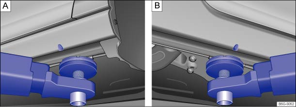 Fig. 206 : Lifting point at the front. : Lifting point at rear for lifting the vehicle using a workshop hoist or floor jack (Golf).
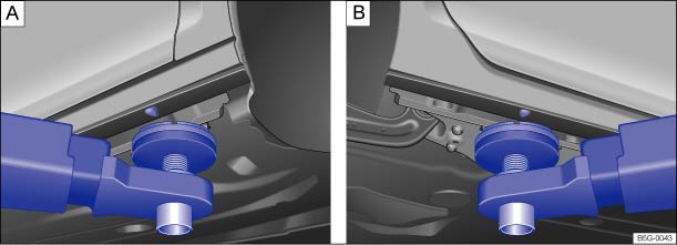 Fig. 207 : Lifting point at the front. : Lifting point at rear for lifting the vehicle using a workshop hoist or floor jack (Golf GTI, Golf R).
The vehicle may only be raised at the lift points shown in the illustration ⇒ Fig. 206 or ⇒ Fig. 207 . If the vehicle is lifted at different points, vehicle damage ⇒ and serious injuries may occur ⇒ .
Workshop hoists that use fluid cushions (receiving platforms) must not be used for lifting the vehicle.
There are many precautions that have to be followed when lifting a vehicle on a workshop hoist or floor jack. Do not try to lift a vehicle on a workshop hoist or floor jack unless you have the training, knowledge, and experience to be able to do so safely.
Information about lifting the vehicle with a vehicle jack ⇒ Lifting the vehicle with the vehicle jack (Golf) .
WarningImproperly lifting your vehicle with a workshop hoist or a floor jack can cause the vehicle to fall off and cause serious personal injury.
Note
Introduction to the subjectIn this chapter you will find information on the following subjects:⇒ Protecting yourself and the vehicle WarningA vehicle breakdown in traffic is dangerous and creates a great risk for you, your passengers, and others.
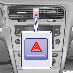 Fig. 208 In the center of the instrument panel: Button for the emergency flashers.Read and follow the introductory information and safety information first⇒Introduction to the subject
Obey all legal requirements regarding protecting a broken-down vehicle. For example, turning on the emergency flashers and wearing a safety vest are mandatory in many countries.
Park the vehicle at a safe distance from traffic and on a suitable surface .
Switch on emergency flashers by pressing the button .
Apply the parking brake to help prevent the vehicle from moving Parking brake (Golf, Golf GTI) or Electronic parking brake (Golf R) (depending on equipment).
Shift the transmission into Park (P) (automatic) or Neutral (manual only) Shifting.
Stop the engine and remove the key from the ignition switch or turn off the ignition with the starter button and remove the key from the vehicle Starting and stopping the engine.
Have all passengers exit and go to a safe location away from moving traffic, such as behind a guard rail.
Take all vehicle keys with you when leaving your vehicle.
Set up a warning triangle or other warning device in order to alert other motorists and cyclists.
Let the engine cool down and get expert assistance if necessary.
If the emergency flashers are on, use the turn signal lever to indicate a direction or lane change, for example when the vehicle is being towed. This temporarily interrupts the emergency flashers.
Always obey traffic laws that govern the use of emergency flashers where you are driving.
If the emergency flashers are not working, a different method – as permitted by law – must be used to alert other motorists and cyclists to the breakdown.
WarningDisregarding the safety-related checklist may lead to accidents and serious personal injuries.
WarningThe vehicle exhaust system and the catalytic converter or diesel particulate filter get very hot. They can cause fires and serious personal injury.
NoteTo help prevent damage to the vehicle if you should have to push it a short distance by hand, never push against spoilers, lights, body panels, windows, or similar parts. Concentrating force on these parts of the vehicle can cause expensive damage that may not always be obvious right away.The vehicle battery will be drained if the emergency flashers are on for a long time – even if the ignition is switched off.
Introduction to the subjectIn this chapter you will find information on the following subjects:⇒ Manually unlocking and locking the driver door ⇒ Manually locking the passenger doors ⇒ Opening the trunk lid from inside the luggage compartment ⇒ Emergency release for the fuel filler flap ⇒ Emergency release for the selector lever lock
The doors and the trunk lid can be manually locked and, in some cases, unlocked if necessary, for instance because the power locking system or the remote control vehicle key malfunctions.
WarningSerious injuries can result if the emergency closing and opening procedures are used carelessly.
WarningCareless opening and closing of the doors, the trunk lid, and the power sunroof is dangerous and can cause serious personal injury.
NoteTo help prevent vehicle damage, carefully remove and properly reinstall parts after emergency locking or unlocking.
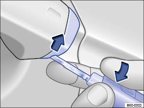 Fig. 209 Door handle on driver door: Removing the lock cylinder cover.Read and follow the introductory information and safety information first⇒Introduction to the subject
When locking the vehicle manually, all doors are locked. To unlock the vehicle manually, turn (counterclockwise) to the unlocking position. When the vehicle is unlocked manually, only the driver door is unlocked. Note the instructions for the anti-theft alarm system ⇒ Power locking system .
The driver door can be unlocked separately from the inside the vehicle by pulling the door handle to open the door ⇒ Unlocking or locking the vehicle from the inside .The anti-theft alarm system, when installed, is not activated when the vehicle is locked manually with the key bit ⇒ Anti-theft alarm system .
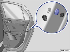 Fig. 210 On the front side of the right rear door: Manual lock, covered by a rubber seal.
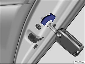 Fig. 211 On the front side of the right rear door: Locking the vehicle with the key bit in the vehicle key.Read and follow the introductory information and safety information first⇒Introduction to the subject
The passenger door and rear doors can each be locked manually. This will not activate the anti-theft alarm system, when installed.
The vehicle doors can be unlocked and opened separately from inside the vehicle by pulling the door handle to open the door ⇒ Power locking system .
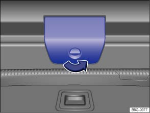 Fig. 212 Inside the luggage compartment: Cover for the trunk lid release.
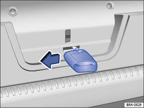 Fig. 213 Inside the luggage compartment: Opening the trunk lid.Read and follow the introductory information and safety information first⇒Introduction to the subject
Read and follow the introductory information and safety information first⇒Introduction to the subject
There is no emergency release for the fuel filler flap. Contact an authorized Volkswagen dealer or an authorized Volkswagen Service Facility for assistance.
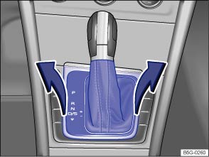 Fig. 214 Removing the selector gate cover.
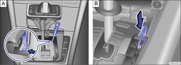 Fig. 215 Releasing the selector lever lock (versions and ).Read and follow the introductory information and safety information first⇒Introduction to the subject
If the power supply fails (due to a dead vehicle battery, for example) and the vehicle has to be pushed or towed, the emergency release must be used to move the selector lever to Neutral (N). You will need the screwdriver from the vehicle tool kit to release the selector lever ⇒ Vehicle tool kit .
The emergency release is located under the selector gate cover on the right side when viewed in the driving direction.
.WarningNever shift the transmission out of Park (P) without first firmly applying the parking brake. Otherwise, the vehicle can start to roll unexpectedly, especially on hills or inclines, and cause an accident and serious injuries.NoteEven with the selector lever is in Neutral (N), the automatic transmission will be damaged if the vehicle is towed (or you let it coast) for an extended period or at high speed with the engine shut off.
Introduction to the subjectIn this chapter you will find information on the following subjects:⇒ Storage ⇒ Contents
When securing the vehicle after a breakdown, always obey all applicable legal requirements.
WarningLoose tools and other items in the vehicle tool kit and a loose spare (or compact spare) wheel may be thrown through the passenger compartment if you brake suddenly or steer sharply or are involved in an accident. This can cause severe injuries.
WarningImproper or damaged vehicle tools can lead to accidents and injury.
Fig. 216 In the luggage compartment: Floor covering raised and secured.Read and follow the introductory information and safety information first⇒Introduction to the subject
The vehicle tool kit and the spare wheel, compact spare wheel, or tire mobility set may be in one of several places under the floor covering in the luggage compartment.
NoteAlways guide the luggage compartment floor covering back down carefully. Dropping the floor covering could damage the vehicle trim and the floor covering itself.Completely retract the jack after use. Otherwise it will not fit in its compartment and cannot be stowed safely.
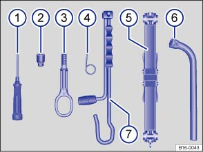 Fig. 217 Contents of the vehicle tool kit.Read and follow the introductory information and safety information first⇒Introduction to the subject
The contents of the vehicle tool kit depend on the vehicle's equipment. The following describes the maximum contents.
Contents of the vehicle tool kit⇒ Fig. 217
Screwdriver with a hexagonal socket in the handle for removing or inserting previously loosened wheel bolts. The screwdriver blade is reversible. The screwdriver may be stored under the lug wrench (if equipped).Adapter for anti-theft wheel bolts (if equipped). Volkswagen recommends that you always carry the adapter for the wheel bolts in the vehicle along with the vehicle tool kit. The code number of the wheel bolt lock is imprinted on the front of the adapter. If lost, a replacement adapter can be ordered using this number. Record the code number of the wheel bolt lock and store it separately from the vehicle.Screw-in towing eye.Hubcap puller clip for removing hubcaps, full wheel covers, or wheel bolt caps.Jack (if equipped). Before putting the jack back in the foam insert, be sure to completely crank the jack down to its original position.Lug wrench (if equipped).Crank (if equipped).The vehicle jack requires no regular maintenance. If necessary, apply multi-purpose grease to the joints of the vehicle jack.
Introduction to the subjectIn this chapter you will find information on the following subjects:⇒ Hubcaps ⇒ Wheel bolt caps ⇒ Wheel covers WarningUnsuitable wheel covers and improper installation of wheel covers can cause accidents and severe injuries.
NoteTo help prevent damage to the vehicle, be careful when removing wheel covers and be sure to install them properly.
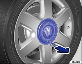 Fig. 218 Pulling the hubcap off.
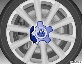 Fig. 219 Twisting the hubcap off.Read and follow the introductory information and safety information first⇒Introduction to the subject
Depending on the vehicle model, the hubcaps can either be pulled off ⇒ Fig. 218 or removed by twisting ⇒ Fig. 219 .
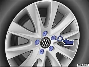 Fig. 220 Pulling cover caps off wheel bolts.Read and follow the introductory information and safety information first⇒Introduction to the subject
The caps are designed to protect the wheel bolts and should be installed again after the wheel change.
The anti-theft wheel bolt (if equipped) has a separate cap. This only fits the anti-theft wheel bolt, but not the standard wheel bolts.
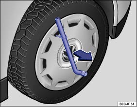 Fig. 221 Pulling the wheel cover off.Read and follow the introductory information and safety information first⇒Introduction to the subject
Before installing the wheel cover, the anti-theft wheel bolt (if equipped) must be screwed into position ⇒ Fig. 223② or ③ in relation to the position of the tire valve. Otherwise, the wheel cover cannot be installed.
Make sure that the valve cutout is aligned with the valve ⇒ Fig. 223① , and press the wheel cover onto the wheel rim. Make sure that the wheel cover is latched onto the rim along the entire circumference.
Introduction to the subjectIn this chapter you will find information on the following subjects:⇒ Preparations for changing a wheel ⇒ Wheel bolts ⇒ Lifting the vehicle with the vehicle jack (Golf) ⇒ Lifting the vehicle with the vehicle jack (Golf GTI, Golf R) ⇒ Removing the subwoofer ⇒ Changing a wheel ⇒ After changing a wheel
Change a wheel by yourself only if the vehicle is parked in a safe location, you are familiar with safety procedures and the technical steps, and you have proper tools available. Otherwise, get expert assistance.
The vehicle jack can only be safely used to change the wheel on a vehicle that has only one flat or damaged tire. If the vehicle does not have the support it needs from 3 fully inflated tires, the vehicle can fall off the jack. If more than 1 tire on the vehicle is flat or damaged, do not lift the vehicle with the vehicle jack. Instead, get expert assistance.
WarningChanging a wheel, especially on the side of the road, can be dangerous. To help reduce the risk of serious personal injury:
Read and follow the introductory information and safety information first⇒Introduction to the subject
If you have a flat tire, move as far away from traffic as possible. Park the vehicle on a flat and level surface where no part of the hot catalytic converter and exhaust system can come into contact with flammable materials under the vehicle, such as dry grass, brush, spilled fuel, etc.
Set the parking brake to help prevent the vehicle from moving Parking brake (Golf, Golf GTI) or Electronic parking brake (Golf R) (depending on equipment).
Automatic transmission: Shift the transmission into Park (P) Shifting.
Stop the engine and remove the key from the ignition switch or turn off the ignition with the starter button and remove the key from the vehicle Starting and stopping the engine.
Manual transmission: Engage a gear Shifting.
Have all passengers exit and go to a safe place, such as behind a guard rail.
Block the diagonally opposite wheel with chocks or other suitable things.
If towing a trailer: Unhitch the trailer from the vehicle and park the trailer properly.
If the luggage compartment is loaded: Remove the luggage.
Raise and secure the luggage compartment floor.
If applicable: Remove the subwoofer Removing the subwoofer.
Unscrew the fastening screw with washer counterclockwise and remove.
Take the spare or compact spare wheel and the vehicle tool kit out of the luggage compartment.
Take off the wheel covers Wheel trim.
WarningDisregarding the safety-related checklist may lead to accidents and serious personal injuries.
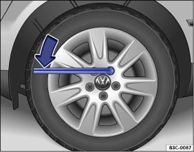 Fig. 222 Changing a wheel: Loosening the wheel bolts.
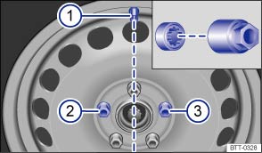 Fig. 223 Changing a wheel: Tire valve ① and installation points for the anti-theft wheel bolt (if equipped) ② or ③.Read and follow the introductory information and safety information first⇒Introduction to the subject
Loosen the wheel bolts only with the lug wrench produced by Volkswagen for your vehicle.
Loosen the wheel bolts only about 1 turn before lifting the vehicle with the jack.
If a wheel bolt does not come loose, carefully push the end of the lug wrench with your foot. Make sure you are standing firmly on the ground and hold on to the vehicle for support.
. .The design of rims and wheel bolts is matched to the factory-installed wheels. If different wheels are installed, wheel bolts with the right length and bolt head shape must be used. The attachment of the wheels and function of the brake system depend on this.
It may not be possible to use wheel bolts from different vehicles of the same model.
On a wheel with a wheel cover, the anti-theft wheel bolt (if equipped) must be installed at points ⇒ Fig. 223② or ③ in relation to the position of the tire valve ①. Otherwise, the wheel cover cannot be installed.
Correctly tightened bolts for steel and alloy wheel rims should have a torque of 88 ft-lbs (120 Nm). After changing a wheel, have the wheel bolt tightening torque checked right away with an accurate torque wrench.
Before you check the tightening torque, replace corroded and difficult-to-turn wheel bolts and clean the threads in the wheel hub.
Never grease or oil the wheel bolts and the threads in the wheel hubs. The bolts can come loose while driving if greased or oiled, even if tightened to the required torque.
WarningImproperly tightened wheel bolts can come loose while driving and cause you to lose control over the vehicle, resulting in accidents and serious injuries.
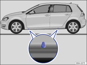 Fig. 224 Lift points for the jack.
 Fig. 225 Jack in position at the left rear lift point.Read and follow the introductory information and safety information first⇒Introduction to the subject
The jack must be positioned at one of the 4 lift points located behind the markings on the vehicle body (2 on each side as shown in ⇒ Fig. 224 ). You must use the lift point closest to the wheel being changed ⇒ .
The vehicle may only be lifted by a jack positioned at one of the 4 jack lift points.
Find a level spot on firm ground for lifting the vehicle.
Switch off the engine. Automatic transmission: shift the transmission into Park (P)) Automatic transmission: Selector lever. Manual transmission only: shift into a gear Manual transmission: Gearshift lever. Then firmly apply the parking brake to help prevent the vehicle from moving Braking and parking.
If towing a trailer: Unhitch the trailer from the vehicle and park the trailer properly.
Straighten the steering wheel so that the front wheels point straight forward.
Block the diagonally opposite wheel with chocks or other suitable things.
Loosen the wheel bolts of the wheel to be changed Wheel bolts.
Find the jack lift point on the vehicle frame that is closest to the wheel to be changed.
Insert the crank ⑦ into the opening on the vehicle jack ⑤.
Crank up the jack so that it still just fits underneath the lift point.
Position the jack so that its base is directly underneath the lift point , making sure that the entire base of the jack rests securely on the ground.
Align the jack and wind up the jack claw at the same time, until the claw cradles the vertical rib underneath the vehicle (arrow).
Continue cranking up the jack until the wheel is just a little off the ground.
WarningImproper use of your vehicle jack can cause the vehicle to fall off the jack leading to serious personal injury. To help reduce the risk of serious personal injury:
WarningDisregarding the safety-related checklist may lead to accidents and serious personal injuries.
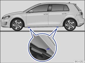 Fig. 226 Lift points for the jack.
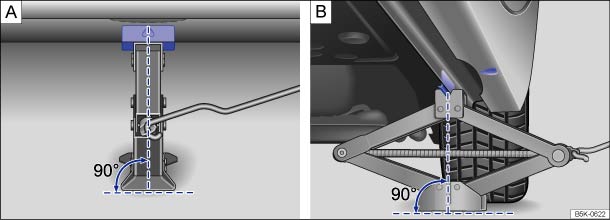 Fig. 227 Jack in position at the left rear lift point.Read and follow the introductory information and safety information first⇒Introduction to the subject
If your vehicle is equipped with a tire mobility set instead of a vehicle jack, please see ⇒ Tire mobility set for instructions on sealing and inflating a tire with the tire mobility set.
The jack must be positioned at one of the 4 lift points located behind the markings on the vehicle body (2 on each side as shown in ⇒ Fig. 226 ). You must use the lift point closest to the wheel being changed ⇒ .
The vehicle may only be lifted by a jack positioned at one of the 4 jack lift points.
Find a level spot on firm ground for lifting the vehicle.
Switch off the engine. Automatic transmission: shift the transmission into Park (P)) Automatic transmission: Selector lever. Manual transmission only: shift into a gear Manual transmission: Gearshift lever. Then set the parking brake to help prevent the vehicle from moving Parking brake (Golf, Golf GTI) or Electronic parking brake (Golf R) (depending on equipment).
If towing a trailer: Unhitch the trailer from the vehicle and park the trailer properly.
Straighten the steering wheel so that the front wheels point straight forward.
Block the diagonally opposite wheel with chocks or other suitable things.
Loosen the wheel bolts of the wheel to be changed Wheel bolts.
Find the jack lift point on the vehicle frame that is closest to the wheel to be changed.
Insert the crank ⑦ into the opening on the vehicle jack ⑤.
Crank up the jack so that it still just fits underneath the lift point.
Position the jack so that its base is directly underneath the lift point , making sure that the entire base of the jack rests securely on the ground.
Align the jack and wind up the jack claw at the same time, until the claw cradles the vertical rib underneath the vehicle (arrow).
Continue cranking up the jack until the wheel is just a little off the ground.
WarningImproper use of your vehicle jack can cause the vehicle to fall off the jack leading to serious personal injury. To help reduce the risk of serious personal injury:
WarningDisregarding the safety-related checklist may lead to accidents and serious personal injuries.
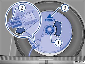 Fig. 228 Under the luggage compartment floor: Subwoofer (if equipped).Read and follow the introductory information and safety information first⇒Introduction to the subject
The subwoofer, if equipped, is located under the luggage compartment floor and must be removed to access the spare wheel.
Raise and secure the luggage compartment floor Storage.
Unscrew the handwheel ① in a counterclockwise direction (arrow).
To release the connector, press and hold the center tab down with one hand ②.
With the other hand, grasp the connector on both sides, and carefully pull the connector out of the socket in the direction of the arrow (magnified view). Put the electric cable aside.
Remove the subwoofer carefully and place in a clean storage location.
Reinstall the subwoofer carefully back into the recess. The tip of the arrow symbol FRONT on the subwoofer ③ must point toward the front of the vehicle
Insert the connector ② into the socket until it clicks into place.
Turn the handwheel ① clockwise to secure the subwoofer.
Carefully lower the luggage compartment floor back into place.
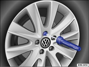 Fig. 229 Changing a wheel: Remove previously loosened wheel bolts using the screwdriver handle.Read and follow the introductory information and safety information first⇒Introduction to the subject
If the tire is a unidirectional tire, be sure to install it in the proper rolling direction ⇒ Tires and wheels .
. Do not tighten them in sequence! Tighten any wheel bolt to begin, then tighten the wheel bolt diagonally opposite the first bolt, and so forth.WarningWheel bolts that are tightened or installed improperly can come loose, causing loss of vehicle control, a crash, and serious personal injury.
WarningImproper use of a compact spare wheel can cause loss of vehicle control, a crash or other accident, and serious personal injury.
Read and follow the introductory information and safety information first⇒Introduction to the subject
The Tire Pressure Monitoring System must be recalibrated after each tire change ⇒ Tire Pressure Monitoring System (TPMS) .
Introduction to the subjectIn this chapter you will find information on the following subjects:⇒ Contents of the tire mobility set ⇒ Preparations ⇒ Sealing and inflating the tire ⇒ Check after 10 minutes of driving
Your vehicle is equipped with a tire mobility set instead of a spare tire.
Tire damage caused by foreign objects or punctures up to about 3/16 in (4 mm) in diameter can be reliably sealed using the tire mobility set. Do not remove the foreign object (screw or nail, for example) from the tire!
After the sealant is filled into the tire, drive for about 10 minutes and check tire pressure again.
Never use the tire mobility set to fill a tire unless all of the following requirements have been met:
Otherwise, get expert assistance.
WarningUsing the tire mobility set on the side of the road can be dangerous. To help reduce the risk of serious personal injury:
WarningImproper use of the tire mobility set can cause a temporary tire to fail and lead to loss of vehicle control and serious personal injuries.
Obey all legal requirements when disposing of used or expired sealant.New tire inflation cylinders are available from authorized Volkswagen dealers and authorized Volkswagen Service Facilities.Read the separate user manual from the manufacturer of the tire mobility set.
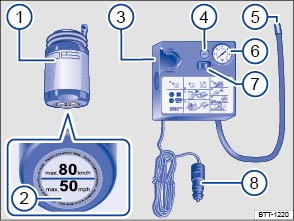 Fig. 230 Basic diagram: Contents of the tire mobility set.Read and follow the introductory information and safety information first⇒Introduction to the subject
The tire mobility set may be stored in one of several places in the luggage compartment (for example, in the side storage compartment or under the floor covering). It contains the following ⇒ Fig. 230 :
Tire inflation cylinder with filling hose and sealantLabel (on the bottom of the tire inflation cylinder) with speed instruction max. 80 km/h/max. 50 mphAir compressorAir release valveInflation hoseTire pressure gaugeON/OFF switch12 Volt plugMay also be integrated in the compressor.
May also be located on the side of the compressor.
Read and follow the introductory information and safety information first⇒Introduction to the subject
If you have a flat tire, move the vehicle as far away from traffic as possible. Park the vehicle on a flat, level surface at a safe spot.
Apply the parking brake to help prevent the vehicle from moving Braking and parking.
Move the selector lever into Park (P) Shifting.
Stop the engine and remove the key from the ignition switch Starting and stopping the engine.
Have all passengers exit and go to a safe place, such as behind a guard rail.
Switch on emergency flashers and use a warning triangle or other device to warn oncoming traffic In an emergency. Observe all legal requirements.
Check whether a repair with the tire mobility set is possible Tire sealant must not be used:.
If the luggage compartment is loaded: Remove the luggage.
Remove the tire mobility set from the luggage compartment.
Affix the label ② from the bottom of the tire inflation cylinder to the dashboard in the driver's field of vision, making sure the label does not cover the instrument cluster or other warning lights and signals on the instrument panel.
Do not remove the foreign object (screw or nail, for example) from the tire!
WarningDisregarding the safety-related checklist may lead to accidents and serious injuries.
Read and follow the introductory information and safety information first⇒Introduction to the subject
. Maximum run time 8 minutes⇒ . .WarningThe tire inflation hose and air compressor can get hot during inflation.
NoteDo not let the compressor run for more than 8 minutes to help prevent overheating and damage. Let the compressor cool down for a few minutes before switching it on again. Let it cool down almost completely before stowing it in the repair kit.
Read and follow the introductory information and safety information first⇒Introduction to the subject
Connect the inflation hose ⇒ Fig. 230⑤ from the air compressor to the tire valve and read the tire pressure on the tire pressure gauge ⑥.
.WarningDriving with a tire that cannot be sealed is dangerous and can cause accidents and serious injuries.
Introduction to the subjectIn this chapter you will find information on the following subjects:⇒ Fuses in the vehicle ⇒ Replacing blown fuses
Due to ongoing development of the vehicle, configuration-dependent allocation of fuses and the combined fuse protection of multiple loads with one fuse, an up-to-date overview of the fuse location per load is not possible at the time of printing. Detailed information regarding fuse box layout is available from authorized Volkswagen dealers and authorized Volkswagen Service Facilities.
In general, one fuse can protect several loads. One load can also be protected by several fuses.
Find out why the fuse blew and correct the problem before replacing a blown fuse. If a newly replaced fuse blows again after a short time, the electrical system should be checked by an authorized Volkswagen dealer or an authorized Volkswagen Service Facility.
WarningHigh voltage systems in the engine compartment can cause electrical shocks, severe burns, and even death!
WarningUsing the wrong fuse, using a blown fuse that has been repaired, and using metal objects in place of fuses to complete the electrical connection in the circuit can cause fires and serious personal injury.
Note
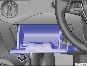 Fig. 231 On the driver side in the instrument panel: Fuse box cover.
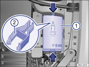 Fig. 232 In the engine compartment: Fuse box cover ① with tweezers ②.Read and follow the introductory information and safety information first⇒Introduction to the subject
Replace a blown fuse only with a fuse of the same amperage (same color and same imprint) and same overall size.
| Color |
Current strength in amps (ATO/MINI) |
Current strength in amps (JCASE) |
|---|---|---|
| Black | 1 | — |
| Light brown | 5 | — |
| Brown | 7.5 | — |
| Red | 10 | 50 |
| Blue | 15 | 20 |
| Yellow | 20 | 60 |
| White or clear | 25 | — |
| Green | 30 | 40 |
| Orange | 40 | — |
| Pink | 30 | 30 |
In some vehicles, there are plastic tweezers for removing fuses on the inside of the fuse box cover ⇒ Fig. 232② .
Note
The vehicle contains other fuses in addition to those mentioned in this section. Have these fuses replaced by an authorized Volkswagen dealer or an authorized Volkswagen Service Facility.
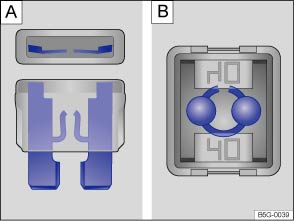 Fig. 233 Blown fuse: : Blade fuse. : JCASE® fuse.
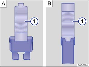 Fig. 234 Removing or installing a blade fuse with the plastic tweezers: : Blade fuse. : JCASE® fuse.Read and follow the introductory information and safety information first⇒Introduction to the subject
In some vehicles, there are plastic tweezers for removing blade fuses on the inside of the fuse box cover in the engine compartment.
.NoteIf a fuse is replaced with a fuse with higher amperage, then damage can occur at various places in the electrical system.
Introduction to the subjectIn this chapter you will find information on the following subjects:⇒ Indicator light
Changing a light bulb requires a certain amount of skill. Therefore, Volkswagen recommends having the light bulb changed by an authorized Volkswagen dealer or an authorized Volkswagen Service Facility. Special training and knowledge are generally required when other vehicle parts must be disassembled to replace a bulb, or when HID – High Intensity Discharge (Xenon) headlights must be replaced.
You should always keep a box in the vehicle with all the replacement bulbs required for traffic safety. Replacement bulbs are available from your authorized Volkswagen dealer or authorized Volkswagen Service Facility. The laws of some countries explicitly require you to have replacement bulbs in the vehicle.
Driving with outside lights that do not work may be against the law.
To obtain the Volkswagen service information necessary to change light bulbs yourself, see ⇒ Volkswagen service information .
Some factory-installed light bulbs in the headlights or the rear lights may have different specifications than conventional light bulbs. Specifications are on the glass bulb or on the metal base.
WarningCrashes and other accidents can happen when you cannot see the road ahead and when you cannot be seen by other motorists.WarningImproper replacement of burned out headlights and other light bulbs can cause serious personal injury.
NoteAfter replacing a headlight bulb or other light bulb, always make sure that the rubber covers or plastic caps have been properly and securely reinstalled to help prevent water from getting into the electrical connections and the headlight housing and damaging the electrical system.LEDs cannot be replaced. Contact your authorized Volkswagen dealer or authorized Volkswagen Service Facility for assistance.
Read and follow the introductory information and safety information first⇒Introduction to the subject
| Lights up | Possible cause | Proper response |
|---|---|---|
|
|
Light bulb of the exterior vehicle lighting not working. | See an authorized Volkswagen dealer, an authorized Volkswagen Service Facility, or other qualified workshop to replace the light bulb that isn't working. |
When the ignition is switched on, several warning and indicator lights come on briefly for a function check. They go out after a few seconds.
WarningFailure to heed warning lights and instrument cluster text messages can cause the vehicle to break down in traffic and result in a collision and serious personal injury.
NoteFailure to heed warning lights or text WARNINGS can result in vehicle damage.Failure of a single LED within a taillight is not indicated. However, the indicator light will light up if all LEDs fail.
Displayed in color on an instrument cluster with color display.
Introduction to the subjectIn this chapter you will find information on the following subjects:⇒ Jump-start terminal ⇒ Using jumper cables
If your engine does not start because the vehicle battery is dead, your vehicle's battery can be connected to the battery of another vehicle to start your engine (jump-starting). Check the battery acid level indicator on the vehicle battery before jump-starting ⇒ Vehicle battery .
You must use jumper cables that meet recognized industrial standards (check information provided by the jumper cable manufacturer). For vehicles with gasoline engines, the cross-section of the jumper cable wire must be at least 0.038 in. (25 mm), or about 3 ga. (AWG).
WarningWorking on the batteries or the electrical system in your vehicle can cause serious acid burns, fires, or electrical shock.
WarningImproper use of jumper cables when jump-starting a vehicle with a dead battery can cause the battery to explode, leading to serious personal injury. To help reduce the risk of battery explosion:
NoteTo help prevent extensive damage to the vehicle electrical system, read and heed the following:
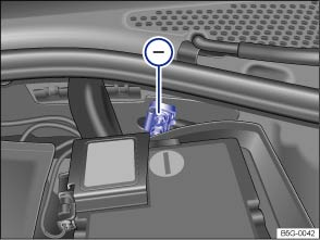 Fig. 235 In the engine compartment: Negative jump-start terminal ㊀.Read and follow the introductory information and safety information first⇒Introduction to the subject
The jump-start terminal for connecting the black jump-start cable is in the engine compartment ⇒ Fig. 235㊀ .
Your vehicle can only be jump-started or be used to jump-start another vehicle via this jump-start terminal.
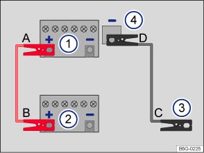 Fig. 236 Diagram for attaching the jumper cables: Dead battery ① and booster battery ②.Read and follow the introductory information and safety information first⇒Introduction to the subject
Key to ⇒ Fig. 236 :
Battery of the vehicle receiving starting assistanceBattery of the vehicle providing starting assistance.Negative jump-start terminal on vehicle providing starting assistance.Negative jump-start terminal on vehicle receiving starting assistance.The dead battery must be properly connected to the vehicle's electrical system.
Make certain that the vehicles are not touching each other. Otherwise, electric current could flow as soon as the positive battery terminals (+) are connected. Use longer jumper cables if necessary.
The clamps on the jumper cables must have good contact to bare metal on the battery terminals.
If the engine does not start, stop the process after 10 seconds and repeat after about 1 minute. If the engine still does not start, get professional assistance.
The procedure for attaching and for removing the jumper cables is described below. Perform each of the following steps only in the order described, which follow the letters shown in the illustration ⇒ Fig. 236 A – B – C – D.
Switch off the ignition in both vehicles Starting and stopping the engine.
Open the battery cover, if necessary Vehicle battery.
Attach one end of the red jumper cable A to the positive battery terminal ⊕ on the dead battery: ① .
Attach the other end of the red jumper cable B to the positive battery terminal ⊕ on the good battery (booster battery): ②.
Attach one end of the black jumper cable C to the negative jump-start terminal of the vehicle providing assistance: ③ (Jump-start terminal), or if that is not available, to a bare metal part of the vehicle providing assistance. This part should be connected directly to the engine block.
Attach the other end of the black jumper cable D to the negative jump-start terminal of the vehicle receiving assistance ④ (Jump-start terminal), or if that is not available, to a bare metal part of the vehicle receiving assistance. This part should be connected directly to the engine block. Attach the clamp to a point that is as far away as possible from the dead battery ①
Route the jumper cables so that they cannot get caught in any moving parts in the engine compartment of either vehicle.
. If the engine does not start within about 10 seconds, turn off the ignition and wait at least 1 minute; then try again. If the engine still does not start, get professional assistance.Disconnect the black (-) cable from the vehicle with the dead battery.
Disconnect the black (-) cable from the other vehicle (vehicle with the good battery).
Disconnect the red (+) cable from the other vehicle (vehicle with the good battery).
Disconnect the red (+) cable from the vehicle with the dead battery.
Close the battery cover.
WarningImproper use of jumper cables when jump-starting a vehicle with a dead battery can cause the battery to explode, leading to serious personal injury. To help reduce the risk of battery explosion:
Introduction to the subjectIn this chapter you will find information on the following subjects:⇒ Towing on a commercial tow truck ⇒ Tips on towing ⇒ Installing the front towing eye ⇒ Installing the rear towing eye ⇒ Driving tips while towing
Observe legal requirements when towing.
Vehicles with Keyless Access may only be towed with the ignition on.
Towing the vehicle when the engine is turned off and the ignition is turned on drains the vehicle battery. Depending on the charge level of the vehicle battery, it is possible that even after just a few minutes, electrical devices such as the emergency flashers may not have the power necessary to function. The steering wheel might lock in vehicles with Keyless Access ⇒ .
WarningNever tow a vehicle without any electrical power.
WarningTowing a vehicle changes the way it handles and brakes. To help reduce the risk of an accident and serious personal injury, note the following:
Note
Read and follow the introductory information and safety information first⇒Introduction to the subject
To help avoid damaging the vehicle, have it towed only by a professional towing company. Read and heed the following information:
Never let the vehicle be towed at speeds above 30 mph (50 km/h).
Never let the vehicle be towed for more than 30 miles (50 km).
. .WarningIt is not safe for children or other persons to ride in a vehicle that is being towed.
NoteThe drive axle rotates while the vehicle is being towed with its rear wheels off the ground. This can damage the automatic transmission.
Read and follow the introductory information and safety information first⇒Introduction to the subject
A towing eye is included in your vehicle's tool kit. This can be inserted in a threaded hole in the front bumper and used when your vehicle is being towed by another vehicle. On most vehicles, there is another threaded hole in the rear bumper, so you can use the towing eye to tow other vehicles as well. Towing a vehicle with a tow bar is safer and easier on both vehicles than using a tow rope. A tow rope should be used only if a tow bar is not available.
The tow rope should be flexible enough to help protect both vehicles from damage. Use a synthetic fiber rope or similar rope.
Attach the tow rope or tow bar only to the towing eye included in the vehicle tool kit for this purpose, or to a trailer hitch.
Check whether your vehicle can be towed at all; see below ⇒ When not to tow your vehicle .
If yes, note the following for the towed vehicle:
Check whether your vehicle can be towed at all; see below ⇒ When not to tow your vehicle .
If yes, note the following for the towed vehicle:
Vehicles with all-wheel drive (4MOTION) should be towed with a tow bar or a tow rope. If the vehicle is towed with the front or rear axles lifted off the ground, the engine must be switched off. Otherwise the powertrain may be damaged.
For vehicles with DSG automated transmission, also follow the directions on how to tow a vehicle with automatic transmission ⇒ Towing automatic transmission vehicles .
In the following situations, the vehicle cannot be towed and must be transported on a flatbed truck or trailer:
A vehicle can be towed only if the electronic steering column lock and the electronic parking brake (if equipped) are released. In case of a power loss or malfunctions of the electrical system, the engine may have to be jump-started in order to release the electronic steering column lock and the electronic parking brake (if equipped).
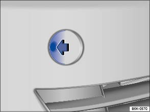 Fig. 237 In the right front bumper: Removing the cover.
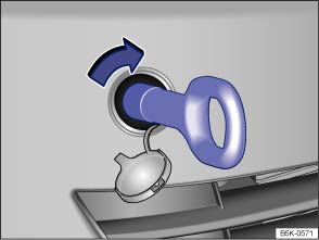 Fig. 238 In the right front bumper: Installing the towing eye.Read and follow the introductory information and safety information first⇒Introduction to the subject
There is a threaded hole for the towing eye in the right front bumper behind a cover ⇒ Fig. 238 .
Always keep the towing eye in the vehicle and stow it securely.
Read and follow the notes about towing ⇒ Tips on towing .
. Use the lug wrench to turn and tighten the towing eye.NoteAlways make sure the towing eye is screwed all the way into threaded hole so that it is secure. If not, it could be pulled out while your vehicle is being towed.
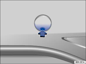 Fig. 239 In the right rear bumper: Removing the cover.
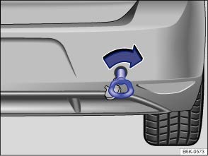 Fig. 240 In the right rear bumper: Installing the towing eye.Read and follow the introductory information and safety information first⇒Introduction to the subject
There is a threaded hole for the towing eye in the right rear bumper behind a cover ⇒ Fig. 240 .
Always keep the towing eye in the vehicle and stow it securely.
Read and follow the notes about towing ⇒ Tips on towing .
. Use the lug wrench to turn and tighten the towing eye.NoteAlways make sure the towing eye is screwed all the way into threaded hole so that it is secure. If not, it could be pulled out while your vehicle is being towed.
Read and follow the introductory information and safety information first⇒Introduction to the subject
Towing requires some experience, especially when using a tow rope. Both drivers must be familiar with the techniques required for towing. Inexperienced drivers should not try to tow a vehicle or to drive a vehicle that is being towed.
Do not pull too hard with the towing vehicle, and avoid jerking the tow rope. When towing on an unpaved road, there is always a risk of overloading and damaging the attachment points.
If your vehicle is being towed, it can still signal turns even if the emergency flashers are activated, as long as the ignition is switched on. Use the turn signal in the normal way. The emergency flashers go off as long as the turn signal is blinking. As soon as the turn signal lever returns to its neutral position, the emergency flashers are automatically activated again.
| ABS | Anti-lock Brake System |
| AFS | Adaptive Front Lighting System |
| AKI | Anti-Knock Index |
| ANSI | American National Standards Institute |
| ASL | Automatic Shift Lock |
| ASR | Anti-Slip Regulation |
| ATA | Anti-Theft Alarm system |
| BAS | Brake Assist System |
| ccm | Cubic centimeter – metric unit of measure for engine displacement |
| CID | Cubic inch displacement – unit of measure for engine displacement |
| cm | Centimeter – metric unit of measure for length |
| CO2 | Carbon dioxide |
| DIN | Deutsches Institut für Normung (German Institute for Standardization) |
| DRL | Daytime Running Lights |
| DSG | DSG automated transmission |
| EDL | Electronic Differential Lock |
| EDR | Event Data Recorder |
| EN | European Norm |
| EPC | Engine control (Electronic Power Control) |
| ESC | Electronic Stability Control |
| g/mi (g/km) | Generated carbon monoxide amount in grams per mile (kilometer) driven |
| GAWR | Gross Axle Weight Rating |
| GVWR | Gross Vehicle Weight Rating |
| HID | High Intensity Discharge headlights (Xenon) |
| hp | Horsepower – unit of measure for engine power |
| kg | Kilogram – metric unit of measure for weight |
| kN | Kilonewton – unit of measure for force |
| kPa | Kilopascal – unit of measure for tire pressure |
| kp | Kilopond – unit of measure for force |
| kW | Kilowatt – engine rating |
| LED | Light Emitting Diode |
| m | Meter – metric unit of measure for length |
| MFD | Multifunction Display |
| MIL | Malfunction Indicator Light (engine) |
| MTBE | Methyl Tertiary Butyl Ether |
| Nm | Newton meter – unit of measure for engine torque |
| PDC | Park Distance Control |
| RON | Research Octane Number – measurement of anti-knock resistance of gasoline |
| rpm | Engine revolutions per minute (engine speed) |
| SAE | Society of Automotive Engineers |
| TSI | Turbocharged gasoline engine with direct fuel injection |
| XDL | Extension of the Electronic Differential Lock system |
| 5S man | 5-speed manual transmission |
| 6S auto | 6-speed automatic transmission |
| 6S man | 6-speed manual transmission |